Business is pretty darned good.

Jim, since we cut a lot of keyseats and keyways, we have machines dedicated solely for this purpose.

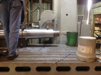
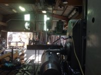
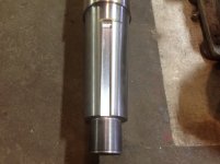
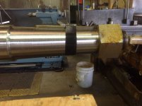
We cut the keyseats in Shafts on our #5 Verticle Mill. You notice the tapered V Block that is bolted to the Mill's table. The shaft is mounted in that block. But the weight is supported by the overhead crane. As the Mill table moves, it pulls the crane along with it. The keyseat is straight with the tape, not the shaft journals.


http://benchrest.com/attachment.php?attachmentid=21751&stc=1&d=1542471225

http://benchrest.com/attachment.php?attachmentid=21753&stc=1&d=1542472148

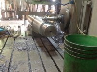
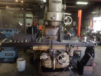
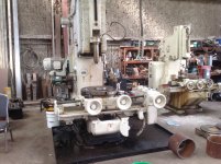
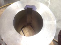
We cut internal keyways on our large Slotter. The head on the Slotter can be angled to match any taper.

http://benchrest.com/attachment.php?attachmentid=21752&stc=1&d=1542471456

http://benchrest.com/attachment.php?attachmentid=21754&stc=1&d=1542472293
 

Attachments

  • image.jpg
    image.jpg
    993.6 KB · Views: 425
  • image.jpg
    image.jpg
    1.6 MB · Views: 416
  • image.jpg
    image.jpg
    944.3 KB · Views: 405
  • image.jpg
    image.jpg
    977.4 KB · Views: 357
Last edited:
Awesome!

Jackie, those parts and equipment are a whole 'nuther world to most of us. It looks like everything you work with requires a crane or hoist to move it.

Out here in the oilfields of West Texas, some of the equipment associated with drilling rigs, pump jacks etc., have always seemed huge to me but I've never seen anything like the stuff you work on that goes on ships and tugs.

Interesting stuff!

Later, Gene Beggs

Gene, if you look at the third picture in my last post, that nut on the shaft is what secures the Prop on the taper.

About 4 years ago we started making those because the ones we were buying were all made in China and were junk.

That is a 4 1/4 diameter 4tpi. We make them any size.

We actually start with a sawed round blank. We trepan a hole in each blank, then, with a special indexing attachment on a 16 inch band saw, we saw the hex. The Machinist then threads them to a master Gage.

It sounds like a lot of work, but we only have around 1.5 hours labor at $100 an hour in each nut, $75 or so worth of material. For a 5 1/2 inch 4tpi nut, we get $550.

You do the math.

Custom Nuts. And the customer is a happy camper....And the next guy who has to work on this job......:D
 
Francis, ductility is a big factor in Prop Shafts. The material is mild steel, 1018. You get the strength needed by the size of the shaft. A typical 9 inch shaft can swing a 90 inch diameter propeller at about 1300 horsepower. The speed is usually around 250 RPM.

All criticle surfaces, the Prop Taper, the Bearing Journals, and the Seal Surface are all Stainless Steel weld.

In lay terms, we Machine the shaft down 1/4 inch to the side in the shape of the finished shaft, then weld it up with 308/316L Stainless using submerged arc welding. We then finish Machine the Stainless Surfaces to the finished dimensions. All other exposed surfaces are coated with epoxy resin fiberglass.

There are solid Stainless Steel shafts, it is made from 17-4 at H11-50 heat treat. The drawback is cost, and it's corrosion resistance is rather low.

Here is a 8 1/2 inch diameter shaft we just rebuilt and are fitting the prop too.

http://benchrest.com/attachment.php?attachmentid=21740&stc=1&d=1542227791
Gotta be in Texas...even the clock on the wall is YUGE! Lol!
 
Gotta be in Texas...even the clock on the wall is YUGE! Lol!

Big in TX

A dude from The Hamptons was down in Youston for a writer's convention...... he spent a liddle too much time at the bar and when he wandered off for a wee he stumbled into the wrong room and fell into the Olympic sized swimming pool......

Ya's could hear him hollering all over the hotel...... "DON'T FLUSH!!! PLEASE, NOBODY FLUSH!"
 
Here is a picture I took today of one of the 2600 HP Tugs being built at SanJac Marine in Houston.

The Shafts have been installed. It will go in the water in about 2 weeks. It will then be placed on Drydock and finished.

The other picture is the next hull being built. It is still upside down on the shipway. They will flip it and place it on building blocks when the first boat is launched.

http://benchrest.com/attachment.php?attachmentid=21794&stc=1&d=1543453705

http://benchrest.com/attachment.php?attachmentid=21795&stc=1&d=1543453756

http://benchrest.com/attachment.php?attachmentid=21796&stc=1&d=1543453806
 

Attachments

  • IMG_2795.JPG
    IMG_2795.JPG
    1.3 MB · Views: 366
  • IMG_2797.JPG
    IMG_2797.JPG
    1.2 MB · Views: 345
  • IMG_2796.JPG
    IMG_2796.JPG
    1.5 MB · Views: 318
Here is a picture I took today of one of the 2600 HP Tugs being built at SanJac Marine in Houston.

The Shafts have been installed. It will go in the water in about 2 weeks. It will then be placed on Drydock and finished.

The other picture is the next hull being built. It is still upside down on the shipway. They will flip it and place it on building blocks when the first boat is launched.


I never cease to be amazed at the mass and weight of such vessels. Man, all that steel. :eek: And I guess every square inch of it will have to be sandblasted and painted with some sort of epoxy coating that will endure the harsh environment they operate in. Can't imagine what one of those costs.

Thanks for sharing

Gene Beggs
 
Gene mentioned that he can't imagine what a boat like that costs. If anybody knows, please tell us.
 
Gene mentioned that he can't imagine what a boat like that costs. If anybody knows, please tell us.

Wilbur, the boat pictured is a 92 ft x 34 ft 2600 horsepower. The typical price of one of these is between 4 and 4.5 million dollars.

With the cost of steel going up, and new emissions regulations being implemented, that could go up as much as 30 percent in the next few years.

That cost is just a starter. Pushboats are extremely maintenance intensive. That brand new boat will start to self destruct the minute it goes into service. These boats usually run the inland waterways such as the Intracoastal Waterway, were the water is pretty corrosive. These boats get banged around a lot handling barges, going in and out of locks, and navigating waters that are barely deep enough.

It is not uncommon for a vessel to have to undergo a major drydocking every three years, and it is not uncommon for a major drydocking, where everything that is worn out or broke is repaired, to cost $500,000 or more.

That is just cost of normal wear and tear. Between major drydockings, there are all sorts of things that can happen that can result in emergency repairs. Bent or broken Shafts and Rudders, along with hull damage are the most common.

Gene mentioned the weight of a boat this size. It will weigh approx 480 tons finished.
 
Last edited:
Wilbur, the boat pictured is a 92 ft x 34 ft 2600 horsepower. The typical price of one of these is between 4 and 4.5 million dollars.

With the cost of steel going up, and new emissions regulations being implemented, that could go up as much as 30 percent in the next few years.

That cost is just a starter. Pushboats are extremely maintenance intensive. That brand new boat will start to self destruct the minute it goes into service. These boats usually run the inland waterways such as the Intracoastal Waterway, were the water is pretty corrosive. These boats get banged around a lot handling barges, going in and out of locks, and navigating waters that are barely deep enough.

It is not uncommon for a vessel to have to undergo a major drydocking every three years, and it is not uncommon for a major drydocking, where everything that is worn out or broke is repaired, to cost $500,000 or more.

That is just cost of normal wear and tear. Between major drydockings, there are all sorts of things that can happen that can result in emergency repairs. Bent or broken Shafts and Rudders, along with hull damage are the most common.

Gene mentioned the weight of a boat this size. It will weigh approx 480 tons finished.

What makes the water more corrosive in the areas they are working?
 
Jackie,

In the first two pictures, that doesn't look like a dry dock, or much of a dry dock to me. Howthehell they get that thing in the water?

Justin
 
Also some real nice Video's on YouTube showing them doing their work.

Thanks Jackie what you post is extremely interesting to me and I always look forward to seeing it.
 
All looks very familiar to me , but on a much larger scale. I chartered for 20 years and my boats were USCG certified vessels 60 and 65 feet long. A 2 inch shaft is all I had to deal with, but we did have the Coast Guard to keep happy. It was a lot of work, but I do miss it. Thanks Jackie for bringing back the memories.
 
I would guess they flood it. i have seen some vids of that type

blades,

One would think, but looking at that cement wall in the background, if that is the water barrier, it doesn't look like it would be very deep. It would seem that the boat's draft would be deeper than that.

Dunno...that's why I asked.

Justin
 
The boat is facing the water, and setting on blocks.

The way this shipyard "launches" them is they have a large beam with 16 large truck tires under it. We will call it a dolly.

They place this under the front push knees. They then lift the back of the vessel up with a large crawler crane. They bring a Drydock lengthways up to the bank and float it untill it is even with the bank. The big crane then gently pushes it onto the Drydock and sets it down. They then sink the dock and float the boat, they raise the dock, remove the dolly, place the correct docking plan for the boat and put it back on Drydock.

Here is a couple of pictures from one launched last year.

http://benchrest.com/attachment.php?attachmentid=21797&stc=1&d=1543539596

http://benchrest.com/attachment.php?attachmentid=21798&stc=1&d=1543539660
 

Attachments

  • IMG_0261.JPG
    IMG_0261.JPG
    2.2 MB · Views: 346
  • IMG_0260.JPG
    IMG_0260.JPG
    2 MB · Views: 374
Last edited:
The boat is facing the water, and setting on blocks.

The way this shipyard "launches" them is they have a large beam with 16 large truck tires under it. We will call it a dolly.

They place this under the front push knees. They then lift the back of the vessel up with a large crawler crane. They bring a Drydock lengthways up to the bank and float it untill it is even with the bank. The big crane then gently pushes it onto the Drydock and sets it down. They then sink the dock and float the boat, they raise the dock, remove the dolly, place the correct docking plan for the boat and put it back on Drydock.

Here is a couple of pictures from one launched last year.

http://benchrest.com/attachment.php?attachmentid=21797&stc=1&d=1543539596

http://benchrest.com/attachment.php?attachmentid=21798&stc=1&d=1543539660

Dude you just get better and better!

Thank You Jackie, I'm like a 4yrold at the zoo
 
Al, that large shaft I mentioned earlier, we are cutting the keyseats now.
On large Shafts such as this with keyseats larger than 2 inches wide, we usually cut them on our big Lucas Horizonal Boring Mill with arbor cutters.

As you can see, the shaft is mounted in a V Block, but all of the weight is handled by the overhead crane. The Mill Table pulls the crane along as the keyseat is cut.

http://benchrest.com/attachment.php?attachmentid=21798&stc=1&d=1543539660

http://benchrest.com/attachment.php?attachmentid=21800&stc=1&d=1543609717

http://benchrest.com/attachment.php?attachmentid=21801&stc=1&d=1543609783

http://benchrest.com/attachment.php?attachmentid=21802&stc=1&d=1543610376

http://benchrest.com/attachment.php?attachmentid=21803&stc=1&d=1543672862
 

Attachments

  • IMG_2799.JPG
    IMG_2799.JPG
    1.2 MB · Views: 216
  • IMG_2802.JPG
    IMG_2802.JPG
    1.3 MB · Views: 287
  • IMG_2798.JPG
    IMG_2798.JPG
    1.5 MB · Views: 353
  • image.jpg
    image.jpg
    1.1 MB · Views: 314
  • IMG_2803.JPG
    IMG_2803.JPG
    1.2 MB · Views: 263
Last edited:
Al, that large shaft I mentioned earlier, we are cutting the keyseats now.
On large Shafts such as this with keyseats larger than 2 inches wide, we usually cut them on our big Lucas Horizonal Boring Mill with arbor cutters.

As you can see, the shaft is mounted in a V Block, but all of the weight is handled by the overhead crane. The Mill Table pulls the crane along as the keyseat is cut.

http://benchrest.com/attachment.php?attachmentid=21798&stc=1&d=1543539660

http://benchrest.com/attachment.php?attachmentid=21800&stc=1&d=1543609717

http://benchrest.com/attachment.php?attachmentid=21801&stc=1&d=1543609783

http://benchrest.com/attachment.php?attachmentid=21802&stc=1&d=1543610376

Jackie,

Is the surface that you're cutting the key seat in indicated parallel with the mill table? If so, how do you do that? Purpose built V-block? Moving the opposite end up and down with the crane?

Justin
 
Back
Top