Threading Problems solved (I think)

adamsgt

Jerry Adams
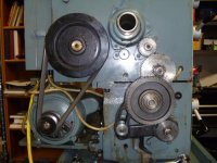
After making a decision on what the gear diagram meant, I installed the threading gears and tightened all the gears down. I tried to use the method Jackie recommended to check the gear setup but couldn't determine how to rotate the chuck exactly one revolution while the half nuts are engaged. Couldn't turn the chuck by hand and the jog button wasn't fine enough. So I just put the last barrel stub in the chuck and started to cut 16 tpi again. Voilà, success. Didn't finish the thread but cut enough to ensure it was correct.
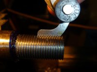
P1000232.jpg

I've printed out the other two threads because there has been so much valuable information contributed by all who responded. Thanks to all of you for your efforts.
 
Great! Glad to hear you solved the problem.
The thread job looks good....... Blake
 
Jerry,
I'm glad you got it figured out and that it's working. I'll have to admit it was entertaining to follow the progress as you went along. Been cold, and iced in here, so it's been nice to have something to read and follow! Merry Christmas!!
 
Jerry, I have to ask. Why couldn't you turn the chuck. All you have to do is put the lathe in neutral and turn it.

My gosh, we have lathes that have chucks that weigh more than your entire lathe, and I can do exactly as I described.

You did put the lathe in neutral??
 
Jerry, I have to ask. Why couldn't you turn the chuck. All you have to do is put the lathe in neutral and turn it.

My gosh, we have lathes that have chucks that weigh more than your entire lathe, and I can do exactly as I described.

You did put the lathe in neutral??

Jackie, could you be more specific about what you mean by putting the lathe in neutral? I disengaged the gears that drive the spindle and I could rotate the chuck but that didn't drive the carriage. The only other control is the lever that controls the direction of the lead screw rotation but putting that in neutral disengages the lead screw. Admittedly I didn't actually try that because I didn't think it would work. I will go to my shop this morning and try that before I go to Friday lunch with my gun crank posse.
 
Jerry,
I'm glad you got it figured out and that it's working. I'll have to admit it was entertaining to follow the progress as you went along. Been cold, and iced in here, so it's been nice to have something to read and follow! Merry Christmas!!

Not all that warm here in Texas either. It's 9:45 AM and it's 44 degrees outside. No ice yet, that comes later. When that happens I stay home. Native Texans have no idea of how to drive on ice. Numerous times I've been behind a driver crossing over a bridge that has ice on it and I see his brake lights come on when he sees he's on ice. Shudder!

Merry Chrsitmas to you too
 
If want to turn the lathe by hand with every thing engaged and measure travel.... i put my lathe in the fastest speed 1300 rpms and it turns real easy by hand. I cannot turn the lathe by hand with the gearing in 72 rpms. ... joe
 
Every lathe ever built has some sort of mechanism that allows you to disengage the spindle with the majority of the gear train, or motor belt in the case of older lathes such as the little South Bends. If it has a high and low range, it will usually have a neutral detent. The older lathes have a spindle pin that you pull.

What kind of lathe are we talking about?..........jackie
 
For threading at very low speeds you probably are in back gear. Simply disengage the back gear lever.

Ray
 
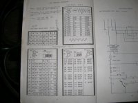
Just got back from lunch. I did try to rotate the chuck by hand but was unable to do so. I used the chuck wrench to get enough leverage to turn the chuck and it did turn but fairly hard. This lathe has a Rutland name on it and the data plate says it was built in Taiwan in 1993. I haven't seen anything pertaining to powering the spindle that has a neutral detent. There are just two levers that give a variety of speed selections. Each lever has three positions which gives nine speeds in each range. I've never tried to use another range as all the speeds overlap. The speed chart has a high and low but I think this is controlled by changing the belt from the motor step pulley. This is a gear head lathe with no back gears. However I did have the speed levers set up for 70 rpm. I'm heading back to the shop and will change that to a high rpm range and see how that works. That's probably the answer.

Here's a picture of the speed chart.

DSCN0661.jpg
 
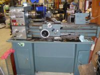
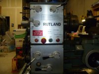
OK, I changed the spindle speed to the highest available and was able to turn the chuck by hand. It was still somewhat hard but doable. Took a few pictures of the lathe to show the controls.

P1000240.jpg


P1000238.jpg


P1000239.jpg

I just don't see anything that would correspond to what Jackie said. However, as you can see, this lathe ain't exactly the cream of the crop.
 
Jerry,
Yeah you say that it is 'not the cream of the crop', but it has a nice large spindle hole (unlike the tiny one on my 10K South Bend) and it cut some nice looking threads in the last thread pic you posted.
You can do a barrel on that machine that I would be hard pressed to do on my South Bend........ Blake
 
Probably the only 'neutral' you have is placing the 2nd lever on the left in the middle position [ the one that controls the direction of rotation of the lead screw ]. This would allow the chuck to turn but the lower gearbox would be disengaged. This of course wouldn't help you do Jackie's test.
 
Probably the only 'neutral' you have is placing the 2nd lever on the left in the middle position [ the one that controls the direction of rotation of the lead screw ]. This would allow the chuck to turn but the lower gearbox would be disengaged. This of course wouldn't help you do Jackie's test.

Yeah Ray, that's exactly what I discovered.
 
Jerry,
Yeah you say that it is 'not the cream of the crop', but it has a nice large spindle hole (unlike the tiny one on my 10K South Bend) and it cut some nice looking threads in the last thread pic you posted.
You can do a barrel on that machine that I would be hard pressed to do on my South Bend........ Blake

Now that I know that I can cut threads on it I have no excuse to not build the both the outboard and bed side spiders. Butch Lambert sent me a nice chunk of aluminum to use for a bed side spider and it's about time that I made it. I also bought a piece of aluminum cylinder to put over the spindle for the outboard spider. It's a very close fit now and doesn't have to be bored out much. There's enough of the spindle hanging out that I've been tempted to just drill and tap that but I don't know if that's a good idea. Thought on that?
 
To do a proper job you would have to remove the spindle from the machine .......

It would be the best way to do it assuming the spindle comes out and goes back in and the bearing preload is reset properly, all without any drama.

If you use the alum sleeve how are you planning on fixing it to the spindle ? I can see a partial split and clamp bolts similar to the way a RF tuner is made to clamp to the bbl. Solid sleeve bored to an interference fit should also work.
 
That little Rutland is not that bad of a machine, maybe better than some of the junk coming out of Mainland China now.

As for the "neutral" thing, try moving the gear shift handle so it is between two gears, if indeed is does not have an actual "neutral" detent. We have three Mazaks that are like that, no actual neutral position, but you just move the high seed-low speed handle between the positions. At least you want be trying to turn the motor back through the gear train.

Looks like you have your problem solved, though. ...........jackie
 
Now that I know that I can cut threads on it I have no excuse to not build the both the outboard and bed side spiders. Butch Lambert sent me a nice chunk of aluminum to use for a bed side spider and it's about time that I made it. I also bought a piece of aluminum cylinder to put over the spindle for the outboard spider. It's a very close fit now and doesn't have to be bored out much. There's enough of the spindle hanging out that I've been tempted to just drill and tap that but I don't know if that's a good idea. Thought on that?

If it were me, I definetly would not drill and tap the spindle.
I would make a nice slide fit of the aluminum onto the spindle.
I would make the aluminum sleeve (spider) with a 1/4 to 3/16 wall thickness and then drill and tap for 1/4-20 TPI at the 90° positions and then use 4 set screws to hold it on the spindle.
I would drill and tap the other end in the same fashion and these are where your adjustment screws will go.
pg
 
Back
Top