setting up to taper bore

JonathanK

New member
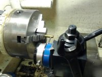
Here is how I have been setting up to taper bore. I use a thin sheet of brass between the the case and chuck, I lightly tighten the chuck with the case neck side in gripping a little of the case body. This leaves enough movement of the case for me to dial it in and be steardy enough to indicate the case length wise. I dial the case in using a couple places on the case to insur that its true. I then set the compound closw to 1 degree and run the indicator atached to the tool post on my compound and turn the compound (little by little .001 or so at a time using my wrench and sofly tapping the compound with one screw on the compound lightly tightened). Once I find where I can run the compound in and out with the indicator staying on 0 or not moving, this should be a good setting for taper boring that perticular case. An other thing I found ou is that my 0 on my compound is a tadoffon my Chinese machine, I chuck up a piece of work and cut it true for a length of 1.5 in. I then use my indicator o n my toolpost and run it the length of my work and find where the indicator doesnt move by adjusting the compound. This seems like the true 0 setting for,my compound. I thought Id run it by you guys before I scribe a new 0 on my machine. Also Im sure you guys know of better ways to set up the compound for taper boring....any help or info or opinions would be greatly appreciated !!!!
Thanks,
Jonathan Kuykendall
 

Attachments

  • IMG_20120115_221300.jpg
    IMG_20120115_221300.jpg
    24.9 KB · Views: 675
If you are setting up to taper bore a chamber body?

1) seat a bullet then chuck on the neck, it will be more stable.

2) But why bother? Taper boring a chamber body adds nothing to the chambering process that I can forsee.
 
If you are setting up to taper bore a chamber body?

1) seat a bullet then chuck on the neck, it will be more stable.

2) But why bother? Taper boring a chamber body adds nothing to the chambering process that I can forsee.

Thanks!
I am setting up here for making case holders for a case trimmer
 
You can acquire a reamer print from the firm that did the grinding on the reamer. PTG shows the amount of taper on the bottom right hand corner of the print. Take this info and calculate the taper per inch as it expressed on the print as taper in twenty inches if I remember correctly. Put a magnetic inicator on bed ways and a magnetic base and indicator on your chuck and traverse the compound for an inch setting compound until you get the correct reading. I forgot to set the compound until after I had already dialed the barrel in on the last barrel I chambered and this method worked perfectly.
 
Thanks for the input...this project is for case holders for LEW case trimmer,I dont have a reamer for a couple of the cases I m making case holdes for yet.
 
A lot depends on the accuracy required, the frequency of the job, and most of all, what you feel is un-necessary work. The method that I have used to get +/- .2 deg. is to indicate a surface on the back side of the compound to match (5*tan. angle). The face that is indicated must be parallel to the inside dovetail surface. Mount a dial indicator in the tailstock drill chuck with the required rods and swivels. Start at the axis of the compound and work toward the handle end. It works better with DRO, When you get a zero at the axis, and 5.000" from the axis in Z, with the X axis reading being equal to the tangent of the angle times five. If you have access to a CMM, check your taper, and make corrections using the(sine of the error)* the distance from the axis, to the indicator point. Some lathes may not allow 5" travel along the compound. Once you get what you want. Write the X axis value inside your Machinery's Handbook. I recut my 16" SB compound.
If the taper is rather long, a pair of ball bearings of the proper dias., a set of depth mics, and that Trig. that you thought you would never need, can be used to check both the dia. and the angle.
Regards,
Bob
 
Last edited by a moderator:
Caution Math Content!!

1. If you still need some help this is a way you can do it. Go here http://www.saami.org/PubResources/CC...0- Rifle.pdf and look up your cartridge. Find the diameters at the shoulder and at the rear datum line, usually .200 ahead of the bolt face. Now notice the distance between the shoulder and this datum line. Now for the math, the first step subtract the shoulder dimension from the rear dimension and divide by two. You want to solve for one side of this triangle. Now use will need to use the Pythagorean thrum! Step 2 take the distance between the shoulder and the datum and multiply it by itself, write that number down. Step 3 now take the number you got in step one and multiply it by itself and write that down. Now for step 4, add the two numbers together and then find the square root. The square root key looks like the division deal that you learned to make in grade school. This number is the square root of the sum of the square of the two sides and represents the length of the hypotenuse in the triangle that you are trying to solve for. Now you are getting close. Step 5, divide the number that you got in step one by the number you got in step four and write this number down. If you have done things correctly the number will begin with a decimal point. What this number represents is the sin of the angle you want to find. Now go here http://www.grc.nasa.gov/WWW/k-12/airplane/tablsin.html and look it up. You will have to extrapolate between the angles to find the correct one or find a more complete sin table with finer break downs. Now let’s go to the lathe, set your compound to this angle with the dial end swung toward the tail stock but not past the lathe centerline. This will let you use a right hand boring tool and run the lathe in forward with the bonus of being able to try the cartridge in the holder. Chuck up a piece of one inch drill rod and mount a .0001 dial indicator in your tool post, then fine tune in angle of your compound with the numbers you got in steps one and four. Run your compound back and forth the length of the distance determined in step four and adjust the angle of the compound angle until you get the dial to read the number you got in step one. If some how you end up with the complementary angle on your compound you’ll see it right away and a little math and you can straighten that out too. With this method you should be able to make one mighty fine case holder that is exactly correct. The rest of the process involving the use of the cross and longitudinal feeds should be self-explanatory once you start the project. Remember that the compound feed will cut this angle, the cross feed and longitudinal feeds affect where the angle is at in relation to your work piece. It takes less time to do most of this than it took to read it.

Math is fun,
Nic.
 
Last edited:
When I put a barrel in the lathe, it doesn't come out until everything is done on that end. That means turning, threading, cone, drill, bore and ream. I bore a straight hole to about .010" under shoulder diameter, and the reamer follows that nicely.

I'm not sure how I would use the reamer during all this to set the taper on the compound.
 
I'm not sure how I would use the reamer during all this to set the taper on the compound.[/QUOTE]

Put the reamer pilot into the bore with the reamer held in the tailstock just like you would hold it for reaming and a .0001 dial indicator in your tool post. Then indicate in a reamer flute, be careful here not to hurt your reamer or indicator point. Adjust the angle of the compound until as you travel the length of the reamer with the compound feed the indicator remains zeroed.

Individual results may vary,
Nic.
 
That's OK, that would mean I set the compound before I drill, indicate and then bore. I don't see the need to taper bore, but to each his own.
 
When I put a barrel in the lathe, it doesn't come out until everything is done on that end. That means turning, threading, cone, drill, bore and ream. I bore a straight hole to about .010" under shoulder diameter, and the reamer follows that nicely.

I'm not sure how I would use the reamer during all this to set the taper on the compound.


The reamer will most certainly follow that hole you have bored, the important thing is that IF you pre-bore, it must be done so that there is no runnout in the hole. I assume you are using a boring bar to make this hole as a drill will always leave a hole with too much runnout for a chamber.

I don't think the taper has to match to case taper to the last second, you just want your reamer to have a nice hole to follow that is going to allow it to cut straight in. If it is off a minute or two, it doesn't seem to bother anything. I stick my reamer into the barrel BEFORE I start drilling and put a piece of brass in my tool holder. I adjust the compound until it looks good to the eye and I run it in and out.

I then move it out of the way and drill an under sized hole first. THEN I go to the tool holder with a boring bar which has been set as previously outlined.

I guess if you are trying to bore a hole good enough to use as a final dimension, I would chuck up a case with a bullet seated and use a feeler gage to check along the case tapping the compound to adjust it to the Nth degree.
 
One time a while back I used to get chatter, not anymore. Then, however I would taper bore the chamber to match the reamer. I set the reamer up in the lathe between centers and indicate the reamer to the compound and then bore the barrel undersize to eliminate the chatter then finish ream. One thing about that, make sure you indicate along the flute of the reamer with the indicator at the correct height, the center height. If it is above or below that, it will not indicate the true taper.
 
I've built a power trimmer modeled off the Giraud unit and for the case holders I've done it a couple of different ways. Using the chamber section or dead barrels is good, if you can get them cheap. For a couple of the wildcats I have, I've replicated the body taper, shoulder, and neck from the reamer print then cut flutes and hardened (O1) and stoned the edges, making my own reamer. You can also do a D-type/half reamer which is a little quicker. In either case you want to have a pilot on the front end. Not really a quick process but it is good for building skills and in all instances resulted in a "chamber" that was perfectly capable of holding the case centered for the trimmer to quickly and repeatedly cut to length and concentrically chamfer the inside and outside of the mouth.
 
I use a sine bar setting gauge I made to fit and lock onto the compound . It pushes two precision posts against the tailstock shaft or a setting bar between centers . The compound is loosend off at it's base so it can swivel.
Using a taper calculation program I use the taper dimentions to calculate the half angle of a taper.
Then using a sinebar program I use the half angle and roll distance between the two posts ( center of one to center of other) on the gauge to calculate the sinebar stack height required to offset the gauge to set the compound at the right angle . This is machined as a ring to drop over the post or a block to hold in place or a feeler gauge can be used. Once the compound is set by the application of the stack height it is locked in place. I can supply you with a plan for the gauge and the two dos based programs that run in windows XP anyway. Once you have a ring made for a certain angle you can set the correct angle in a few seconds.
The main issue is that the side of the compound has to be inline with the compound dovetail travel . Set up a dial indicator and check the travel accuracy . If it is out more than you can tolerate you will need to mill the side straight to the dovetail .
Indicating on the reamer is fine but what if the barrel is already in the chuck and you don't want to take it out and start all over again so this is a method that can set an accurate angle while the barrel is still in the chuck or for turning external or boring internal tapers. I guess you could also hold the reamer in a tail stock chuck to indicate on it .
 

Attachments

  • Compound  taper attachment.jpg
    Compound taper attachment.jpg
    24.9 KB · Views: 237
  • taper.zip
    31.6 KB · Views: 159
  • sinebar stack heights .zip
    30.9 KB · Views: 172
  • Help file.txt
    400 bytes · Views: 153
  • Help file.txt
    397 bytes · Views: 127
Last edited by a moderator:
Back
Top