Shipyard stories

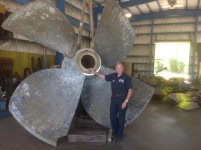
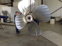
Here is a Picture of a large marine bearing thatI am machining. It's for a 13 inch shaft which we are repairing.


http://benchrest.com/attachment.php?attachmentid=20157&stc=1&d=1507909959

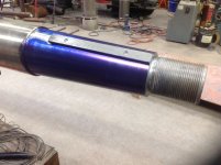
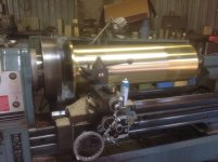
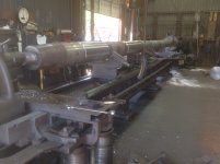
Here is the shaft being finished machined in our 34 ft Lehmann Lathe after welding up the worn surfaces.

We also had to straighten this puppy. They had backed into some submerged bulkhead sections and bent the shaft about 1/8 inch at the prop taper.

http://benchrest.com/attachment.php?attachmentid=20158&stc=1&d=1507910120
 

Attachments

  • image.jpg
    image.jpg
    893.4 KB · Views: 712
  • image.jpg
    image.jpg
    1.1 MB · Views: 579
Last edited:
Jackie,

Thanks for pictures. It's those post's that have brought back a lot of good memories.

I think it's easy to tell I've had a good time sharing them.

Mort
 
Last edited:
The finish on the bearing surface closer to the tail stock appears to be a little different. Change of feed/tool?

Curious and just asking.

Mort
 
The finish on the bearing surface closer to the tail stock appears to be a little different. Change of feed/tool?

Curious and just asking.

Mort

You have a good eye. That part isn't getting machined. This is a Stern Tube Bearing, (the support at the hull intrance). It is only 32 inches long. After I turn the OD, we will take it over to our big saw and saw it off to length. The shame is that drop is pretty much useless.

They are delivering the prop over in the morning. It's about 12 1/2 ft in diameter. We have to refit it to the shaft.
 
Last edited:
Jackie does the Prop need to be lapped onto to the taper to achieve the proper amount surface contact.

JLouis
 
Jackie does the Prop need to be lapped onto to the taper to achieve the proper amount surface contact.

JLouis
 
Jackie does the Prop need to be lapped onto to the taper to achieve the proper amount surface contact.

JLouis

They have to be hand fit with grinders and sanding drums.

It's very labor intensive.

The taper bores of the props get warped when the blades have to be re-pitched due to damage.

We are set up to do this. We have a trained crew, 2 men, who we have taught to do this.
 
Lou,

The props they bring in are something to see.
Mort

I went over to a local wheel shop and looked at this thing last week. If you notice, it has no keyway. It hydraulically installs and relays on the taper to drive it.

http://benchrest.com/attachment.php?attachmentid=20159&stc=1&d=1508017896

The problem is, it would not pump up for the installation. The tapered bore, (.600 in 12.00 inches,) has enough warpage to where the hydraulic oil is leaking before the hub expands.

It's off of a large 10,000 HP Z Drive Unit. Since it is impossible to fit it in place, we are going to to make a mandrel identical to the shaft and fit the bore to it. This will not be easy, as the fit will have to close to 100 percent.
 

Attachments

  • IMG_2114.JPG
    IMG_2114.JPG
    1.3 MB · Views: 646
Ship Props

Jackie, people don't realize how big a 12 foot prop until they see one.

Don't know what a relay is on the taper, and is .600 in 12 inches a standard?

That is going to be a time consuming job. I have three 5 to 8 inch 3 sided concave scrapers used for babbit. If you think they will be of any help, I will send them right down...they even have wood handles.

Mort

I have to start proof reading my post.

That is supposed be "rely", not relay. In other words, it relys strictly on the interference fit of the taper to drive the prop. If properly installed, the taper fit is the equivelent of about .015 interference fit. That's a lot.

That .600 inches in 12.00 inches is proprietary to this particular companies props. The industry standard for standard keyed propellers is .750 inches in 12.00 inches for shafts under 6 inches diameter, and 1.00 inches in 12.00 inches for shafts over 6 inches diameter. In the industry, we just say "three quarter inch to the Foot" or "One inch to the foot".

You are correct. This is going to be a tough job, and it has to be done correctly. That is why they called us.
 
Last edited:
notch?

Jackie the blade to your right has a corner cut out of it that the other 2 that are in the picture don't have. Is this to balance the prop? Does the other blade that is not in the picture have the same notch?
 
Jackie the blade to your right has a corner cut out of it that the other 2 that are in the picture don't have. Is this to balance the prop? Does the other blade that is not in the picture have the same notch?

That's the reason the prop was removed. It will have to be repaired by the wheel shop before we fit it.

They know the prop won't reinstall hydraulically because they had massive leakage taking it off. They had to use a jack and strongback in combination with the hydraulic expansion to get it off of the shaft.

That is one of the problems with these types of installations. They work great, right up untill the time they don't.
 
I would call it surface adhesion more than interference fit.

The same thing that allows gauge blocks to be wrung together.

The smoother and tighter mating the surface the more surface adhesion comes into play.

Try and pull a set of gauge blocks directly apart instead of sliding them over each other.

It is the actual press fit that drives the Prop. There is thousands of ft lbs of torque involved in driving the prop.

The typical way a prop such as this is installied is they first tighten the Prop as firmly as possible on the taper with either the prop nut or keeper plate, which ever it has. Then, they induce the hydraulic oil by extremely high pressure so the oil film not only expands the hub, but gives the two metals a oil film to slide against each other. While inducing this hydraulic pressure, pressure is applied by either the prop nut or keeper plate. They are able to advance the prop up on the taper by at least 3/16 inch more in most cases. When they release the hydraulic pressure, that is the equivalent of around .010 to .012 inch press fit. The Prop nut or keeper is then tightened and locked to keep it there.
 
Last edited:
Thanks for the description Jackie one would never imagine being able to acheive that much of a press fit even being possible but now I understand how that mechanical system can be achieved and indeed work if done properly.

JLouis
 
Thanks for the description Jackie one would never imagine being able to acheive that much of a press fit even being possible but now I understand how that mechanical system can be achieved and indeed work if done properly.

JLouis

Louis, this type of interference fit installation is pretty common on large items. The generic name for it is the SKF system, because SKF developed it years ago.

There are variations of the system, different manufacturers change a few things to make it proprietary.

These systems are not so prevalent in most of the Inland Tugs we work on. The vast majority of the couplings and propellers are keyed taper fits and tightened with a large propeller nut as heat is applied to expand the hub.


http://benchrest.com/attachment.php?attachmentid=20164&stc=1&d=1508121093

http://benchrest.com/attachment.php?attachmentid=20165&stc=1&d=1508122327
 

Attachments

  • IMG_1613.JPG
    IMG_1613.JPG
    1.4 MB · Views: 646
  • IMG_0873.JPG
    IMG_0873.JPG
    1.4 MB · Views: 571
Last edited:
Jackie, how is the hydraulic pressure applied? Through the shaft or through the prop's hub? Or another means?
I tried to google the system & didn't find what I was looking for.
Keith
 
Jackie, how is the hydraulic pressure applied? Through the shaft or through the prop's hub? Or another means?
I tried to google the system & didn't find what I was looking for.
Keith

It varies from manufacture to manufacture. Some have a oil port in the Prop with channels to feed the oil through the hub and between the hub and shaft. The shaft is smooth.

Other systems have a oil port in the end of the shaft that leads to channels cut in the shaft to feed the oil between the shaft and hub.

Most of the systems utilize a 40,000 to 50,000 psi pump to install and remove the prop. There is not a lot of volume involved, as even in a prop the s large, the actual amount of oil involved is quite small.

These systems work great as long as the tolerances are maintained. They also work best in an inviroment where vessels see little damage while in service. In other words, you can install the equipment and not have to remove it for as Long as 5 years.

In vessels that run in inviroments where things get tore up on a regular basis, such as a typical inland push boat, they are not very practical. A standard taper with a key does the job just fine.
 
Last edited:
Back
Top