
This has been discussed on several threads and since the last one was deleted I decided to bring it up again.
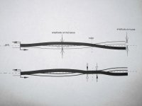
The attached upper pict shows the accepted shape a barrel assumes when vibrated and in the lower pict the "straight" or "parallel" node shape. These are exaggerated in that typically a rimfire would have a few tenths (.0001) amplitude at mid barrel while the muzzle might move a few thousandths (.001). The force to start these vibrations is the moment at the receiver generated by recoil. To get the barrel to flex into a section that is parallel, or nearly parallel to the axis, at the node would require the application of forces as shown in the second view. These forces would have to reverse direction as indicated by the black arrows against the barrel in the black position, and the white arrows against the barrel in the white position.
Half of such forces could come from a moving bullet but a bullet passing through the curved shape shown would tend to push the barrel into a greater angle with the axis. They could also be applied by clamping a rigid sleeve around the node area. Finally they could result from just adding a larger diameter barrel through this section. A larger barrel would flatten, or make straighter the whole curve.
Bottom line is that the most likely shape for a vibrating barrel is shown in the upper picture. The lower shape, while not impossible would be very difficult to achieve in a conventional barrel.
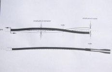

")