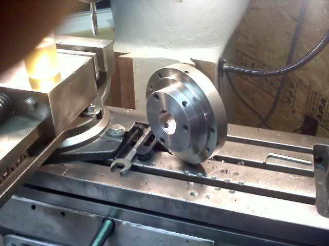
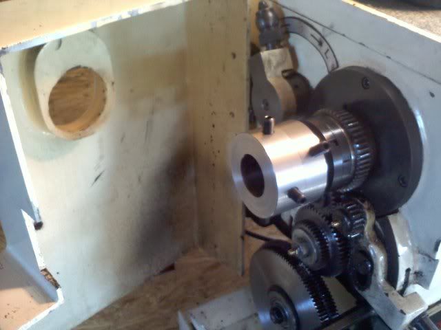
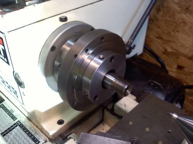
Finished my cone tool

skeetlee

Active member
Here is a little tool some of you might have read me talking about. I will use this tool to check my cone depth when chambering a barrel. I will make another tool just like this one, but a little shorter to check head space with a PT&G go gauge inserted in the chamber. I said i would post a pic when i completed this so here it is. Enjoy and please let me know what you think. remember take it easy i am still learning, And this stuff is way hard for me. LOL!! Lee
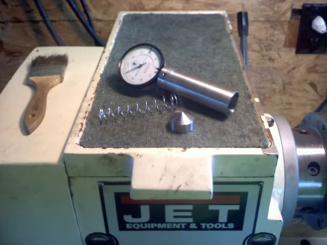
conetool009.jpg


I will have a 30 degree cone and a 25 degree cone depending on what action i am chambering for. I thought about making something for Remington type chambers as well? I know these tools are simple to make, but they give me lathe time and i really enjoy making them. Its amazing what you learn each time you turn the machine on. One thing i am already learning, is that i wish i had a heavier machine with more Pony's! Maybe in time. I am actually grateful i have what i have. perfect to learn with. I also just about bet when the time comes i can still make good shooting barrels on this little machine. Anyway enjoy. Lee

One more thing i forgot to mention. You cant see it but under the set screw in the front, on the dial shaft i cut a flat spot with my mill so the set screw has a nice flat spot to set against. This way, with the tight reamed 3/8" hole i dont think the gauge will ever come loose.
Also one thing i ran across while making this tool was that i had to have right around .004 clearance between the cone and the bored shaft so the cone could ride smoothly up and down the bored shaft. I tried to get away with .002 clearance but my machine wouldn't cut smooth enough. Does that make since, or am i not doing something properly? .002 clearance just wouldnt slide. .004 slides real nice, so thats what i had to do. Would HSS tooling make a difference here?
 
Last edited:
Skeetlee, Nice looking gage ! I have one almost exactly like it and I followed Mike Bryant's pictures of what he uses to make mine. Works great. You may not have to make a separate gage for checking over a go/nogo gage if you just machine the tip on your cone gage flat to about a .400 diameter. That way the gage will measure both. It sounds like you really enjoy what you're doing!! Keep makin' chips, it IS the best way to learn!! Good things to you, Rich
 
One more thing i forgot to mention. You cant see it but under the set screw in the front, on the dial shaft i cut a flat spot with my mill so the set screw has a nice flat spot to set against. This way, with the tight reamed 3/8" hole i dont think the gauge will ever come loose.
Also one thing i ran across while making this tool was that i had to have right around .004 clearance between the cone and the bored shaft so the cone could ride smoothly up and down the bored shaft. I tried to get away with .002 clearance but my machine wouldn't cut smooth enough. Does that make since, or am i not doing something properly? .002 clearance just wouldnt slide. .004 slides real nice, so thats what i had to do. Would HSS tooling make a difference here?

Properly machined 0.0002" clearance should slip nicely.

Would HSS, properly ground do better? What do you think??????

And you said your Dad was hard-headed?
 
LOL... YEP!!!!


Quigley
Yep, you are correct. All i have to do is make a different insert for the go gauge to read from. Why didnt i think of that?? " Were that little picture of the cartoon slapping himself up against the side of his head" Been a long day. I also am just about done with the front and back spiders. Should finish up tomorrow. They are also turning out really really good. Ill post some pics when they are complete. Lee
 
If you move your cursor over the cased set in the second link, a magnified view is shown. Looking at the various bit shapes it seems to me that they each have their own number. for instance on the left side there are a 6 and a 9. As you probably already know, the letters that follow the numbers, HHS, stand for high speed steel. I would guess that the numbers are specific to this manufacturer, to facilitate ordering individual pieces.
 
Lee,

I wouldn't waste my time of money on any of the import HSS tooling. Most of it is just plain junk. Sorry Grizzly. Check out _bay. There is usually lots of used tooling on there. I was just looking the other day at some. I bought a box of assorted stuff for about $15 awhile ago. It is all name brand stuff. Same way with carbide inserts, you can usually get them dirt cheap when you can find what you need.

Joe Hynes
 
Spiders are done. Took most of the day. here is what i came up with.

spiders003.jpg


spiders002.jpg


These pieces are very simple by design really, but i think they will prove to be effective. On the out board spider i will replace the long screws up against the spindle with set screws. I wasn't sure how i was going to connect this spider to the spindle and after some thought, and discussion with a friend, i decided that i would just drill a detent into the spindle shaft for the set screw to rest in and tighten against. There are two of these opposite each other. Seems to be super tight, so i dont figure they will ever move under power. There they are. I had a nice weekend of machining and now its about time to go back into the real world of city work. Have a good week fellas. Lee
 
Last edited:
Ok now i am all done. LOL!! This might not be all that exciting for most but i am so excited i bet i don't sleep tonight. LOL!!! Last pic i promise. Lee

barrelinspider008.jpg


By the way. I didnt chamber the barrel that is in the spider. I am however making this barrel my fist victim. I will set this barrel back and re cut the chamber a bit as my first barreling project. Lee
 
Last edited:
A suggestion on your left end spider, or anyone elses. Increse the od, or shorten the set screws before you are either beat up, or picked up by the rotating spider legs. A suggestion, if the bore is large enough, is to turn a slip fit dia. that goes inside the spindle bore and is attached to the barrel by your flush screws. I have seen a lot of blood let in shops since '66. Many of the incidents were hard to understand, and some were truly unbelievable. My son used to call me "Safety Man", until he started laying 72" concrete sewer pipe in the bottom of 40' deep ditch.
That is nice looking work. Grinding a piece of M3, or M43 hss steel to cut properly is getting to be a lost art. Finish the edges with a medium India stone, and add a slight radius to improve the finish. This applies to endmills also(.005"-.010" rad.).
Regards,
Bob
 
Thanks for the tips Bob. The screws in the back are temporary. I ordered the proper lenght set screws and holding screws with brass inserts yesterday. I am not sure what an India stone is but i will check into that. I am having a ton of fun with all this, and i hope i am not wearing out my welcome with all the pics and questions. The new will wear off in a couple years. LOL!! No, i just think this is part of the hole experience with rifles. Brings the madness to a new level that has a lot of self gratification that no amount of money can buy. I have always been one with a lot of self pride in my work no matter what i am building. Right or wrong, i can always be sure i gave the attempt a 110%. Lee
 
what does the FORM 1 and FORM 4 and so on actually mean? I want to try some HSS tooling i just dont know whats what yet.
The only reference to a “Form 1” or “Form 4” that I know of, is that these are forms used by the BATF to conform to the National Firearms Act of 1934. The form 1 has to do with the manufacture of a class III firearm. The form 4 has to do with the transfer of a class III firearm from a dealer to the registered owner. A class III firearm meaning a "silencer, machine gun, short barreled rifle, etc."

I have not seen anything in this thread that has to do with the NFA, so I am not sure if this is the kind of information you are looking for. FWIW, I am familiar with them.
 
A suggestion on your left end spider, or anyone elses. Increse the od, or shorten the set screws before you are either beat up, or picked up by the rotating spider legs. A suggestion, if the bore is large enough, is to turn a slip fit dia. that goes inside the spindle bore and is attached to the barrel by your flush screws. I have seen a lot of blood let in shops since '66. Many of the incidents were hard to understand, and some were truly unbelievable. My son used to call me "Safety Man", until he started laying 72" concrete sewer pipe in the bottom of 40' deep ditch.
That is nice looking work. Grinding a piece of M3, or M43 hss steel to cut properly is getting to be a lost art. Finish the edges with a medium India stone, and add a slight radius to improve the finish. This applies to endmills also(.005"-.010" rad.).
Regards,
Bob

I can't agree with this enough.

I caged my spider. Barring that I used to wrap electrical tape around it. Cheap insurance.

al
 
Spiders are done. Took most of the day. here is what i came up with.


spiders002.jpg


These pieces are very simple by design really, but i think they will prove to be effective. On the out board spider i will replace the long screws up against the spindle with set screws. I wasn't sure how i was going to connect this spider to the spindle and after some thought, and discussion with a friend, i decided that i would just drill a detent into the spindle shaft for the set screw to rest in and tighten against. There are two of these opposite each other. Seems to be super tight, so i dont figure they will ever move under power. There they are. I had a nice weekend of machining and now its about time to go back into the real world of city work. Have a good week fellas. Lee

I would either go to two screws at right angles to each other or 4 screws on the outboard spider to clamp it to the spindle.

Fitch
 
I have two screws straight across for each other holding th outboard spider on to the spindle and it isnt going anywhere. Very solid for sure. I started my very first barrel job tonight and it is going very smooth. All that is left is to cut the chamber tomorrow morning then off to the bench to see how it does. I couldnt have asked for anything more at least up to this point. heck i am even a couple months ahead of where i thought i would be we i started this journey. The barrel should be great. I didnt have any trouble indicating or with anything else. I hope the chamber cutting goes as smooth as the rest of it has. I was getting a little fuzzy this evening so i decided to walk away for the night. I will report tomorrow. Lee
 
Fitch, a thought. That 'two opposing screws in detents' idea isn't quite as weak as it appears at first glance IMO.

I see your problem, and raise you a thought.......... picture this; the collar is turned to a fairly tight slip fit, screws and detents line up directly and now you tighten 'er all down. It's a wicked massive collar on a fairly light hollow shaft. Wouldn't tightening the setscrews deform the hollow shaft for a solid friction fit everywhere BUT where the setscrews bear? Like squeezing the center of a balloon inside a Quaker Oats container..... not all bad?

Granted I'd have shimmed the shaft out a smidge when I drilled the detents, then removed the shim so they'd pull inwards upon tightening, but dunno as it would matter.

whaddaya' think?


al
 
I would either go to two screws at right angles to each other or 4 screws on the outboard spider to clamp it to the spindle.

Fitch

IMO, clamping screws to hold the spider to the spindle shaft are not needed on the outboard spider because;

1) the spider should only be mounted when being used to stabilize a barrel, otherwise it is a safety hazard.

2) adding clamp screws to fasten the spider to the spindle could cause the assembly to vibrate whereas if it were a snug slip fit the joint would be self-deadening.

3) if used as in 1 above, once the outboard end of the barrel is dialed in the screws that clamp to the barrel will hold the spider in place.
 
When I made mine, I drilled 2 sets of 4 holes, tapped all 1/4-28. One set for securing to the spindle nose with set screws and the other for the adjustment screws. They were drilled in alignment with each other, and the ID of the spider is the same as the spindle. I never take it off unless I need to take the side cover off the lathe. I do take the adjustment screws out, or they will fly out!
 
Well I did it. My very first rifle barrel is done and it even shoots!! Its pretty cold here today so we didnt shoot it much but what little we did shows real promise. I couldnt be any more happy. Lee
 
Back
Top