Z
Zirok
Guest
Hi
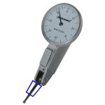
I am doing a project using dial test indicator.
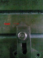
As seen in Image 1, I have clamped the part in such a position that it is 45 degrees to X & Y axis.
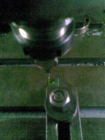
Now as shown in Image 2, I go 20 mm offset from the zero point (Zero Point is shown in blue color) & move in Y axis until reading is shown on dial.
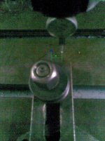
On similar grounds, I go to 20 mm offset from zero point in opposite direction (see image 3 ) & move in Y axis until reading is shown.
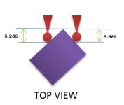
The machine movement in Y axis from Zero Point should be same in both the conditions as mentioned above. But there is variation of 0.453 mm in both the positions (Refer Image 4).
In short, the dial test indicator needs feeds of different values to create the same reading on dial.
We have ensured that the dial clamped is perfectly parallel to Y axis, so there is no issue of contact Point Error.
Can we conclude the Dial as A unbalanced Dial ?
I think this problem has never been noticed by anybody in history till date
How can this happen & what should be the error & how to compensate that error. ??
It is definitely not a Co-Sine Error (Refer Image 5). It is clearly visible that the angle of lever arm is almost 90 degree to the part.
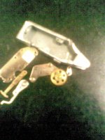
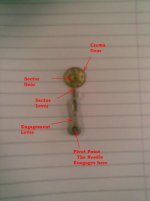
To know more, I had a broken Dial Test Indicator & then disassembled all the stuff to know actually how the dial mechanism works. ( Refer Image Internal Assembly )
As you can see In Image 6, how the mechanism works. It doesn’t seem to be a unbalanced dial. It is a simple mechanism & logically there should be no error.
Need help


