Dusty Stevens
Hollow Point Dispenser
Could someone explain to me the science behind this HSS/carbide observation? I've heard this before and I'm open to input but I have not personally experienced this in my career. For me, setup rigidity and cutter geometry are the most important factors and cutting tool material only determines maximum surface speed and fracture/wear resistance. The only times I can recall higher speed improving cutting performance is with some high temp stainless materials where high chip heat improves chip flow and in cases where an RPM change breaks a harmonic cycle.
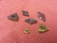
Could it be what you are really experiencing is a difference in cutting tool geometry? There are a lot of carbide inserts out there with less than desirable cutting edge geometry for an engine lathe with marginal rigidity.
The answer is yes. A very good geometry tool and bit as you know is very expensive. Most people buy phase 3 toolholders and inserts and just suffer thru blaming it on carbide inserts and never try a nice toolholder spec'd out by a tool man for their speeds and material