N
NesikaChad
Guest
Oky doke. I have a Winny that a guy sent me to have a new crown put on. No biggy there. Through the course of the conversation he also mentioned that his scope base (adjustable style) is burning up the vast majority of it's travel range in order to maintain a mechanical/no wind zero.
I agreed to take a looker at his action and report what I found and correct it if needed.
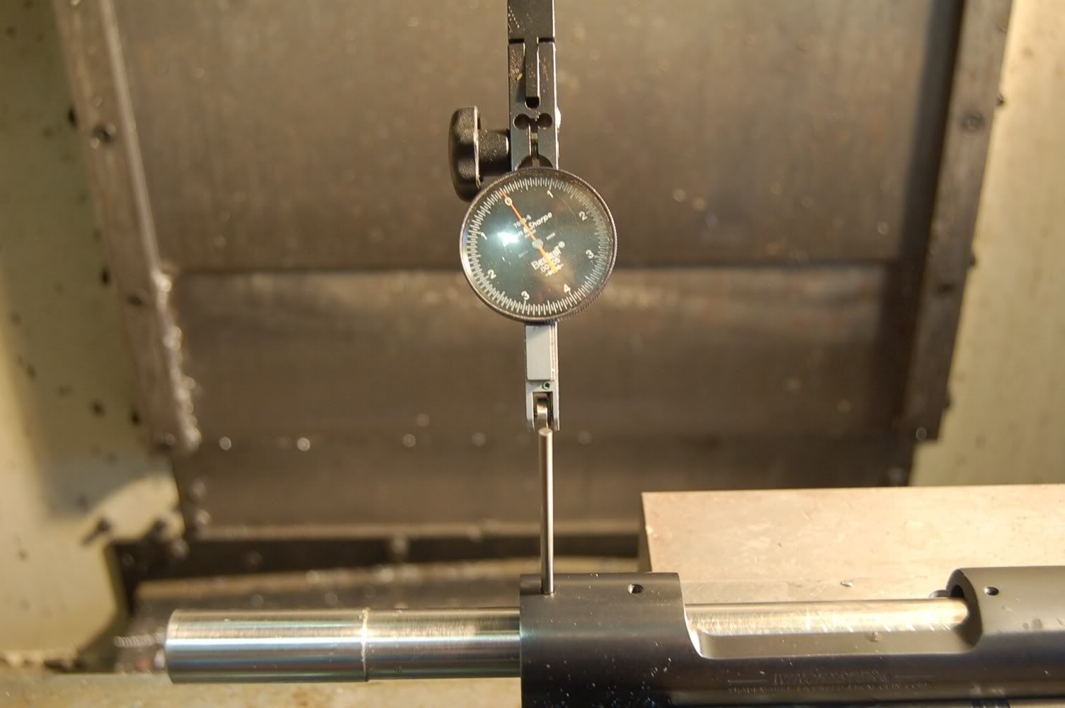
So, here's what I got. I mounted by B/S .00005" resolution indicator to the bottom of the spindle on my mill. I mounted the action in the vise, inserted a mandrel that fits super snug and indicated down the side of it while banging away on the vise with a mallet till the mandrel (bore center) was running parallel to the X axis of the machine.
Next I got out the gauge pins and sorted through them till I found one that would barely go into the base hole. I have to really yank on it to get it back out.
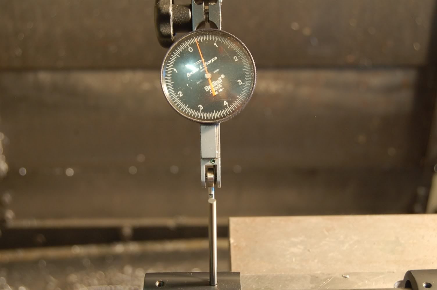
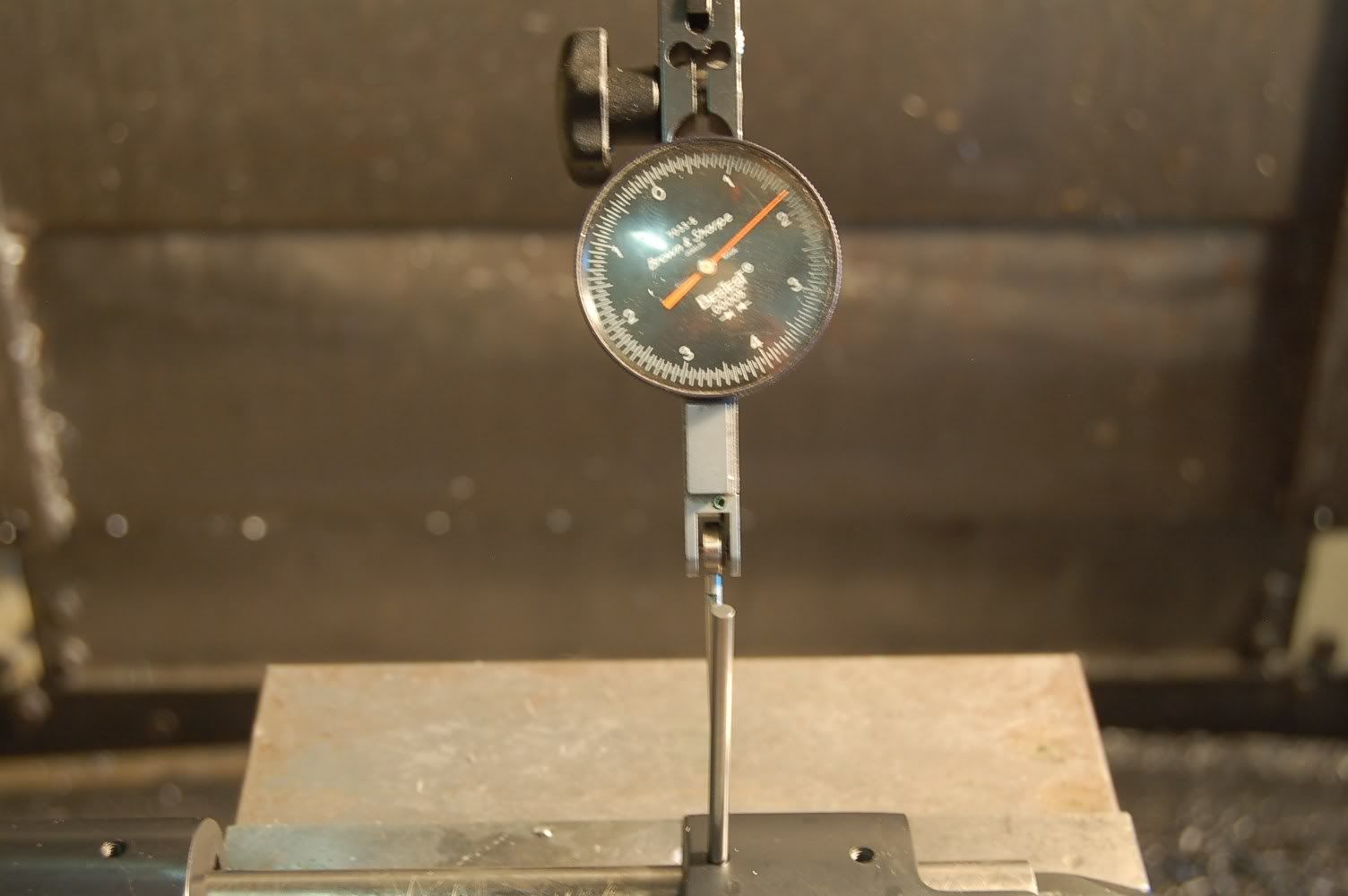
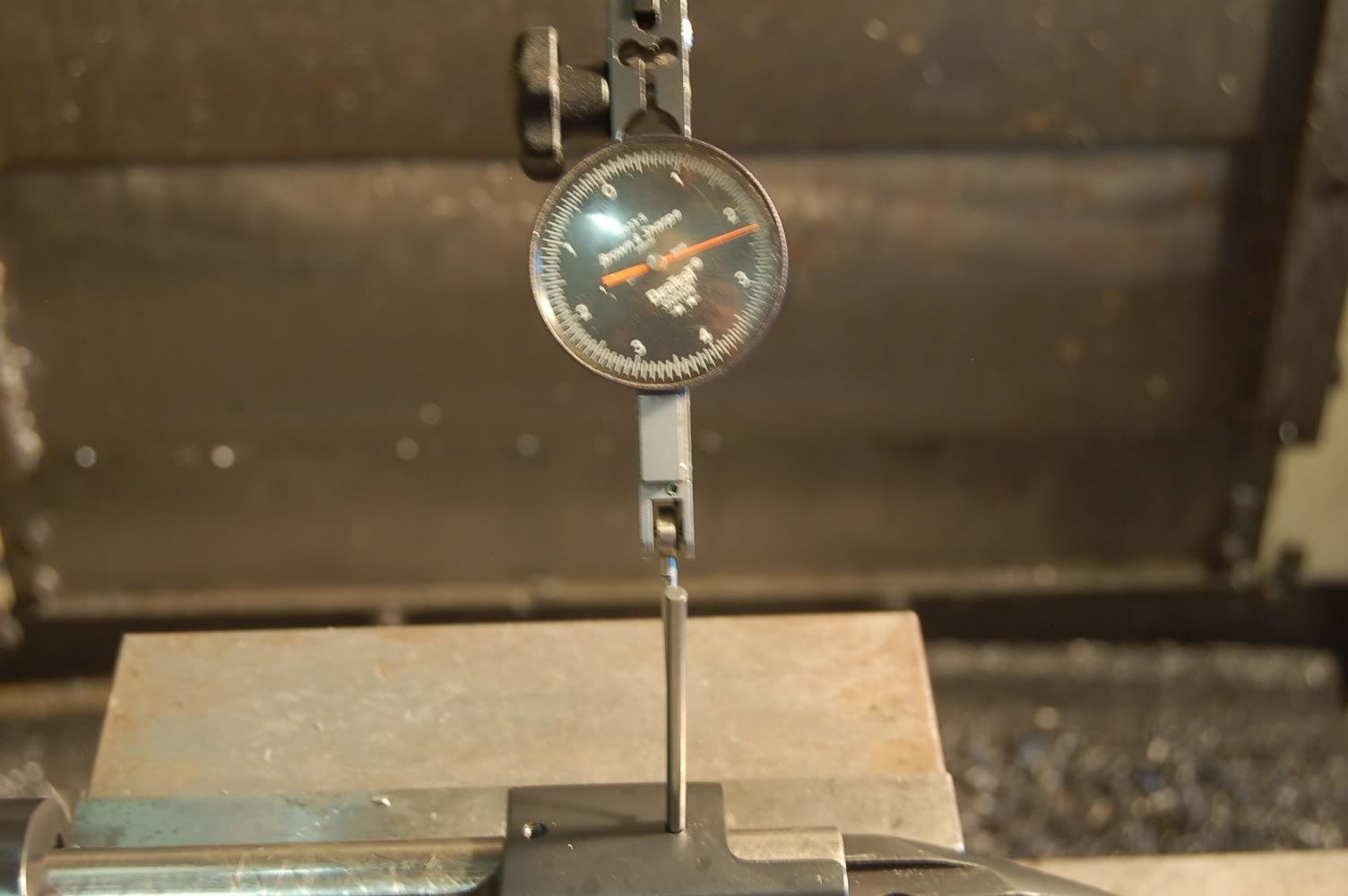
I then just laid the stylus against it and zero'd the bezel on the indicator using the Y axis jog on the machine. Then I went to the next hole, inserted the pin and ran the machine in X only just to see what the deviation is on the indicator. I repeated for the remaining two holes.
I checked it twice two ways. Using the DRO of the machine and zeroing the position of the indicator each time with the Y jog and by just leaving the Y alone and moving in X only and taking a direct reading off the indicator.
They didn't mirror one another exactly, but it was pretty dern close. Within a couple gillionths. I don't expect absolute repeatability as I am dealing with moving parts. I do however feel pretty confident that I'm getting a reasonably close (within .0005") idea of just how parallel the base holes are to the centerline of the receiver.
With the front hole at zero the rear hole was +.0024" The middle ones just followed suit incrementally.
I've included a few photos to illustrate what I'm trying to explain.
I guess my question is, I've never done it this way before (I'd always swept the holes on pins prior) but I don't really see any reason why it's flawed or skewed. From what I can tell the problem does not lie with the receiver holes. The center to center distance on the outer holes is 5.25" inches for this particular action. At 1000 yards a one minute of angle deviation comes out at .0015" at this distance (5.25"). With the action at .0024" I'm going to call that 1.5 to 1.75 minutes at the most. (I'm too lazy to go back and figure it out)
What I'm getting at is the math isn't pointing towards the base holes as the culprit for why he's eating up most of his lateral adjustment on his base.
Just for giggles I left the action in the vise and ran the indicator across the face of the receiver. I get a deviation of .0004". Again, it's not looking like its an action problem.
I conclude either his barrel is a bit crooked or there's something wrong with the scope or bases.
2nd opinions are never a bad thing though so feel free!
Thanks germs!
C


Last edited by a moderator:

