How come this won't work?

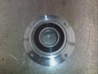
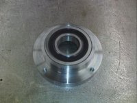
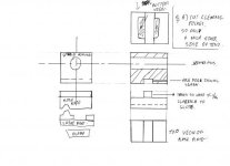
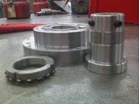
I'm making another hub now for the bearing to be pressed in. It will have a flange with holes drilled and tapped in 4 places. Then I plan to make a plate with an oversize hole for the hub to slip in. A hundred thousandths bigger hole should be plenty. Also in the plate, I will drill over-size holes in the same bolt-circle as the other 4 holes in the flange. That will let the hub move about in the plate. Indicate the bearing and lock it down. I dont see where you need jacking bolts to move the bearing. I would just snug the bolts, and give a light tap with dead-blow hammer. Once its indicated, and locked down, all should be good. Right?


OK, it's starting to come together BUT.......

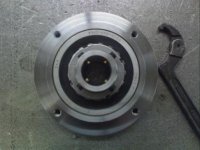
So you get the sliding plate with the pressed in bearing centered up "close", let's say (just for the discussion) that it indicates .010 high and .010 off-center......you're evidently indicating off of a previously turned bar....... Do you preload the bar upward to take out slack in the bearing?? Is the bar walking in the chuck or is it bending?..... so anyway, now you will adjust the bearing to center using a deadblow hammer instead of jacking bolts.

What are the implications of tapping on the unit that's fastened to the lathe ways? Tapping on the bearing? Could it be better to drill some "spud holes" in the plate so that you can jack it around using a pointed pick or punch?

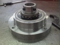
So now you're locked in and it should be all good right :) now how much play is really in that bearing? And how's it going to hold tolerance? and how will you take out play? And how will the spider bolts not distort the bearing race? (BTW I can't imagine trying to hang the bearing in a hole using jacking/spider bolts bearing on the outer bearing race! :eek: It'd be like centering up a balloon between bulldozers!)

I'm just watching with interest to see if this can offer any utility over a good steady........Right now I can't see a way to maintain the necessary accuracy.

cool idea, but.......

opinionsby

al
 
Just finished the hub for the spider.

Alinwa, this hub has the bearing pressed in as you can see. The whole hub will move in the plate. To dial in the bearing, all you would need is a long bar coming out of the chuck. Once you have it dialed in, then you could hang an indicator off the bar and sweep the bearing by turning the chuck. To move it, all you would need is a light tap on the flange of the hub. I didnt mean to sound as if I was going to beat the pee out of the bearing itself. It doesn't take much to move a couple of thousandths. Then she's locked down.

As far as the play goes in the bearing, I cant answer that yet, but I'm sure with quality bearing like the one used, it shouldn't be any worse than the spindle bearings. Also I believe the walls of the spider will be thick enough, that distorting the inner bearing race will not be an issue. Afterall, its not driving the barrel, its only holding center. And I don't think it requires excessive amounts of force to do so. If you were taking really heavy cuts, then maybe problems could show up.

This is probably about as far as I will get on this project for a couple of days, but I will post pics as I get them. If this project works, then great!! If not, I haven't lost a thing, and we'll all know not to bother with it.
 

Attachments

  • spiderhub1.jpg
    spiderhub1.jpg
    31 KB · Views: 302
  • spiderhub2.jpg
    spiderhub2.jpg
    28.8 KB · Views: 300
ben's drawing

the upper have should be spilt in 2 ! like a tail stock body this is to allow for for ajustment in center hight , and the horizontal axis !

here is mine !

you need the tenon to make the adjustments to the Z axis , this is done buy file ( very softly with a smooth file on the 2 1 inch tabs in the base of snipdle housing ! )

advince in setting the alinments ,( al this is for you as well )

trun a lenght of bar that a good fit in the bore , place the said bar in the bore ( it should be a push fit buy hand with little or no slop ) with a clock on the sadle set this to .000'' to +.0005 with ths sadle z movment on side and the top ) top can be set buy scaping or grinding, packing shims that up to you :eek:

hi i have just seen you useing hubb's they will give you a lot of a justment !
with out shim or packing for hight ! but you will need the tenon to set the side alinement of the secondry head
( much of what i have said below well be able to be done with the hub)
once you have done that, then

buy a lenght of 1 inch or lager silver steel the appox lenght of a barrle you wish to chamber !


plave one end in the 4 jaw and clock it true , while other end is suppeted in the secondry spindle clock secnond end true !

now with the clock on the sadle clock the side of the silver steel , set the secondry spindle housing so side of bar read zero at head stock and to +/- .0005'' ( with the base plate fixted to the bed ) lock the housing in this postoion

now clock the top of the the bar ! this ( if you make it low youcan shim it up to the correct hight )
 

Attachments

  • img009.jpg
    img009.jpg
    20.5 KB · Views: 285
Last edited by a moderator:
Just finished the hub for the spider.

Alinwa, this hub has the bearing pressed in as you can see. The whole hub will move in the plate. To dial in the bearing, all you would need is a long bar coming out of the chuck. Once you have it dialed in, then you could hang an indicator off the bar and sweep the bearing by turning the chuck. To move it, all you would need is a light tap on the flange of the hub. I didnt mean to sound as if I was going to beat the pee out of the bearing itself. It doesn't take much to move a couple of thousandths. Then she's locked down.

As far as the play goes in the bearing, I cant answer that yet, but I'm sure with quality bearing like the one used, it shouldn't be any worse than the spindle bearings. Also I believe the walls of the spider will be thick enough, that distorting the inner bearing race will not be an issue. Afterall, its not driving the barrel, its only holding center. And I don't think it requires excessive amounts of force to do so. If you were taking really heavy cuts, then maybe problems could show up.

This is probably about as far as I will get on this project for a couple of days, but I will post pics as I get them. If this project works, then great!! If not, I haven't lost a thing, and we'll all know not to bother with it.

Excellent work

Use standard fit class for shafts bearings and there will be no problem with the bearing.
 
Thanks guys, but I still have quite a bit of work to do yet. I'm having trouble locating a plate that I can bore for the hub. I'd love to have an 8" wide piece, that would give me almost 1.5" per side after I bore the 5" hole. I found a piece of 6", but that will end up too thin for me. I've got a buddy who owns a plasma cam, he said he has some 1/2" thick stock, and would be happy to burn me two pieces. Then I could take those two, weld em together, and finish the bore on the mill. Rather have a piece 8" wide and 1" thick.

Life isn't always easy though.
 
most be sqared up or they'll be trouble

if you dont mind me asking are you going to weld the plate to a base with the tenon on it?

as if the plate is not true to the head stock then the spider will woble on the job (barrel) not a good thing !

what i out lined in my last reply is how we set steed rest at the factory , so they dont mark the work peace being turned

in your case the spiders tip will keep rocking on barrel and may cause chater , or the spider to losern ot bothe

hope the sketch helps !
 

Attachments

  • img011.jpg
    img011.jpg
    18.1 KB · Views: 231
I Have To Ask

All of this is in leu of just using a steady rest on a truly round work piece, or on a spider that is secured to any work piece.

Sooner or later you just have to ask, "why"????.......jackie
 
Hey Jackie, remember what you said in an earlier post about being able to dial in a barrel dead true in a steady-rest. But still be way out due to deflection. Thats one of my biggest reasons. Either way, the headstock is too long to perform thru-spindle chambering.

With the spider method, I think it will be easier and faster to set a barrel up. I think it will be more accurate, because my indicator will tell me exactly where the barrel is. And I think it will be easier to check and re-check alignment between machining operations.

P17p14enflield, When I set the plate up, before locking down that is, why can't I take an indicator, place it on the crossfeed, and run it back and forth on the plate until I get it square?

Better yet, I could use the bar in the chuck that I would use to tram in the bearing, and sweep around the face of the bearing, by turning the chuck. That way, I know dog-gone well it is perfectly square with the chuck. Once it is square, then I could center the bearing.
 
yes that way will work ! iam just used to using test bars at work !
the cross feed will work but should be just a bit out as lathes are ment to face i bit concave , but as you say at enough to make a lot of defrefance
good look iam dieing to see the finished artical , iam show it well work great :)
 
Last edited by a moderator:
All of this is in leu of just using a steady rest on a truly round work piece, or on a spider that is secured to any work piece.

Sooner or later you just have to ask, "why"????.......jackie

I don't think that most folks have thought through the steady-rest concept. I've heard people say, "but there's play in the bearings".... There's NOT! Once you've got the steady adjusted in it automatically takes out all the play, it bears each race to one side every time.

I can't imagine turning a piece that's just floating in the bearing race.... the only reason it feels "tight" is because it's riding on grease!

al
 
just playing

Al , a bearing with no play is called siezed !!!!!!!:)
 
Ok, I know some of you have been anxiously waiting on more pics, so here is where I am now. Just finished making the spider shaft to fit in the hub. As you can see in the pics, instead of a snap-ring like in the first hub, I threaded for a spanner-nut. After completing the shaft, all I had to do was press the shaft in the bearing, screw on the spanner-nut, and lock her down.

Now I have to concentrate on a plate to mount the assembly to... I think I have it all figured out though..;)
 

Attachments

  • SpiderHubParts.jpg
    SpiderHubParts.jpg
    23.9 KB · Views: 249
  • SpiderHubAssembly1.jpg
    SpiderHubAssembly1.jpg
    24.7 KB · Views: 247
  • SpiderHubAssembly2.jpg
    SpiderHubAssembly2.jpg
    22.5 KB · Views: 246
What about the Muzzle end of the barrel ?

I have read "all" of this link, and the comments are dead on, "very" enlightening. The Machine work is Beautiful, and the concept is good thinking, BUT ? What about the other end of the Barrel ? How are you going to dial it in ? I have found that no matter what Mfgr. does the barrel - they are not concentric, ID to OD, this means that something is going to be "wobbeling around" someplace. Through the headstock is the only way I see every thing being dead on concentric. I know - there are those of you that will only do it this way or that, but in 45+ years of machine work, I have never got a Steady Rest to work to "0", no matter what I did, and was getting paid exceptionally well to do it. A Steady REST is just that a steady rest, get your centers and then turn loose of it if at all possible. You are working to do the best you can with what you have I know, but I have my reservations on it - just my point of view, not trying to rain on your pirade, good luck. :)

I have seen several forums that are talking about doing barrel work, chambering and crowns, some will only do it in a steady rest. Some of their ideas I have incorporated into my work on barrels. I just have a hard time seeing the concentricity being perfect at both ends if you are not able to dial in the opposite end of the job. I haven't done any "F" class barrels yet, most of my work is on the hunter class rifles. I try to get them dead "0" every time, both ends and it seems to pay off when they are finished and they shoot into one hole. I treat every re-barrel or instalation as if I were the shooter, and I want it as perfect as I can get it.

Great input to all of you . .
 
Hey Phantom, thats an easy one. All you do is set up the muzzle end in the steady rest first. Once you dial it in, (from the bore) you can turn a small tenon on the OD, which would be concentric to the ID. Then put the shank you just turned in the chuck, dial it in. Then with the chamber end in the steady rest, dial it in, and life is good.

If you do a search on here about the steady rest method of chambering, you will see that thats how most guys on here do it.
 
looking good

pearidge i like how it looking ! aim dieing to see the mounting plate ;)

thinking it should work grate, i would have probly made the hubb bit longet my self but i done really know why, i would have lock nut the end away from spider ( this is just me liking to follow old convention that dont really have any founding)

have good one
 
Ok, I know some of you have been anxiously waiting on more pics, so here is where I am now. Just finished making the spider shaft to fit in the hub. As you can see in the pics, instead of a snap-ring like in the first hub, I threaded for a spanner-nut. After completing the shaft, all I had to do was press the shaft in the bearing, screw on the spanner-nut, and lock her down.

Now I have to concentrate on a plate to mount the assembly to... I think I have it all figured out though..;)

Hey, can you make me one of those for my boat trailer?

Just joking.

Looks good.

Ben
 
Back
Top