How come this won't work?

P

pearidge

Guest
Hopefully I'm not reinventing the wheel here, but I wanted to try a different approach to the Steady-Rest Setup. My headstock is too long, and I really don't like running a regular steady-rest unless I have to. Especially on precision rifle barrels. Now I know some of you use them with great results, and my hat is off to you, but I just don't care for it. I haven't seen anyone post pics of one like this, nor have I read about any spiders designed this way. I think this way is easier to dial in a barrel, because your indicator will tell you exactly where it is at all times. If the pics are hard to make out exactly what I did, I'll try to explain.

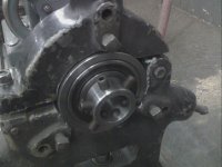
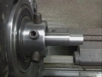
First, I made the hub the same OD as my Steady Rests ID. Then I bored it on each side for a 6210 Bearing. Got a good fit and pressed those two in. Then I made a shaft to go through the ID of the bearings with a step on one end. Pressed the shaft in the bearings all the way to the step. Then I cut a groove for a Snap-Ring. Now the shaft cant move back or forth. Set the mill up with an Indexing Head and drilled and tapped 7/16-20 holes in 6 places.

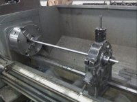
Now, I was wondering if the bearings would have too much runout or play in them that would cause alot of chatter, so I cut a piece of 3/4 Polished Shafting and set it up as if it were a 27" barrel. Took a few cuts on the end just to see if it would raise sand on me. And belive it or not, it didn't. I took one fairly heavy cut with a high feed with no squealing, and no chatter. Hopefully, I can set a barrel up the same way without any problems now.

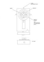
As always, I welcome any questions or comments you may have. And criticism too!! I still have a little bit of work to do yet, one thing is if you look at the close-up pic of the steady-rest, (pic 4) you will notice that its not all the way closed. Thats because the bore isn't perfectly round. But I can relieve that easy enough.

So what do you pros think? Worthwhile, or a total waste of time? Be honest.. LOL...
 

Attachments

  • SteadyRestSprider2.jpg
    SteadyRestSprider2.jpg
    27.2 KB · Views: 1,210
  • SteadyRestSprider4.jpg
    SteadyRestSprider4.jpg
    22.9 KB · Views: 1,096
  • SteadyRestSprider3.jpg
    SteadyRestSprider3.jpg
    23.8 KB · Views: 997
Looks like a great idea with a couple of modifications.

That concept for a bearing supported spider chuck in the steady rest combined with a 4J or spider chuck on the lathe spindle has the ability to allow you to use any of the theoritical concepts for aligning the bore in the lathe in a steady rest. I'd have to use that on my lathe if I wanted to do a barrel shorter than 19", or if I wanted to use the Gritters alignment method on my 9" South Bend which has a tiny spindle hole. In fact, seeing the pictures, I may make one of those for my SB just because it would be a fun project.

I'd suggest using a 4 bolt spider in the bearing instead of a six bolt spider because that will be much easier to align. I'd also suggest using a spider chuck or 4J on the spindle so that you can adjust that end as well.

Thanks for the pictures.

I have a couple of friends that have lathes with headstocks that are too long that I'll send the url to.

Fitch
 
Fitch

Great idea and it works but it's not new. For that matter there isn't much that hasn't been done before. I know smith's that work on shotgun barrels that did that years ago. Looks great BTW. There's been work around here when I wished I had something like that. Just never took the time to make one.

Dave
 
I never thought of pressing a collar into the steady- I just figured to use a tube that ran on the steady points with a hub inside- I think your way is easier. As long as that bearing doesn't allow the hub to move around and induce runnout, I think it's a great idea. Chamber up a barrel and see how little runnout it ends up having. What is the quality of that bearing?

Thanks for pointing me this way Fitch

You're welcome. I found this web site that has good information on bearings, a reasonable selection, and what look like reasonable prices.

http://www.vxb.com/page/bearings/CTGY/20mm-and-more

Fitch
 
The bearings I used are SKF, (6210 2RS) and I might have used something different, but like I said, I wanted to test the idea, so I made do with what I could find.

Slugger, the hub isn't pressed in the steady-rest. I was afraid that if I had it too tight, that I might crack the casting when I started to crank it down. As a matter of fact, after I used it on the rod, I could remove it by hand after opening the steady-rest back up.

Tooley, how come you've been keeping this a secret all this time? Just kidding...:D

Frwillia, I could just have easily used 4 bolts instead of 6, but I feel its easier to fine tune with 6. Plus you have more holding power. Although, all you are really doing is centering up the bore. Its not driving your barrel of course.

One thing I started to do differently, and I may yet, is make an inner shaft that is threaded on one side for a spanner nut. Then I could tighten the bearings up, rather than just let them ride under a snap-ring. And if I did that, I would have to make a spacer to go over the shaft, between the inner bearing races, so that you could lock the bearings onto. Without the spacer, you could easily squeeze the inners too far, which could lead to bearing failure. Right now, all that is overkill. Seems to do just fine, but I will let you know.

Another option is to pop out both inner seals, put a grease fitting in the center, and keep it greased that way. You wouldn't have a mess because you would keep the outer seals in.

Keep the feedback coming fellows!!
 
I like the idea. Thought about doing something similar, but just never have gotten around to it. Would come in handy for me on anything shorter than about 24". Like has already been mentioned I'd go to a 4J and only use 4 bolts in the spider. May also want to make some caps or studs of brass or copper for that spider as well just to keep from marking barrels.
 
Hmmmm

We work with spiders all the time in our shop. It is one of the easiest ways to get a initial round spot on a long flexable shaft forging or a piece of hot rolled steel. But we just run ours on a regular three or four leg steady rest.

One thing I might ask. How will you get the barrel dead in the center of your lathe?? I see adjustments to true the barrel, but no means to shift the entire assy in the steady rest.

But then, maybe the hole in the steady rest is dead in alignment with the lathe spindle after it is bolted down. Not many are........jackie
 
Last edited:
Neat and clever,

and not a lot of work to build. I'd call it my "secondary headstock" or something like that.
You have room to add two more setscrews to the spider, making it a 4 screw if you wanted to do that.

Jay, Idaho
 
I would have to agree with Jackie here.
Yes you can use the spider chuck to set the stock to run true but unless the bearing is exactly inline with the headstock bearing and then the both of them are inline with the bedways it's not running axialy true. This is a common misconception/problem with a normal steady rest as well, you must set the work to run true THEN apply the steady rest ensureing no movement of the job has occured.
What you would need to do is before every job use a very heavy test bar in the headstock and then using a dial indicator mounted on the end of the test bar to dial up the ID of the bearing. Once this bearing or even the whole steady was adjusted to run true it could then be used. OF course this also assumes that the bedways are lined up witht the test bar as well.
Without wanting to rain on your parade, without doing the above the chances of it runing true would be minimal at best.


Cheers
Leeroy
 
Jackie
Leeroy

I had been thinking about the same issue. Some how the bearing assembly has to lined up between centers.

Dave
 
Last edited:
The spider in the steadyrest has been around for a long time. This was probably one of the first improvements to precision chambering after the benchrest games demands starting putting pressure on gun work inside the barrel. It is still not a cure all for alignment for maximum accuracy.

That is why through the spindle chambering is superior to any current method. Maximum advantages of the through the spindle method requires the barrel's bore to extend out of the headstock on both ends. There are several compromise methods for lathes with long headstocks but having the barrel bore exposed to the probe of a dial indicator, on both ends, is the best...so far.
 
Believe me guys, if my headstock was short enough to allow thru-spindle chambering. That's what I would do without any hesitation. But right now I don't have that luxury. And like I said in the first post, I still have work to do.

When I said that the bore in the steady-rest wasn't perfectly round, I knew when I discovered it that it was gonna be a problem. Also, I know it cant be perfectly aligned with the spindle bearings. Its close, but I doubt its perfect.

Heres what I'm thinking now, maybe I could machine 3 pockets in the spriders hub for the steady-rest fingers to go into. Then I could adjust it. Of course, I would have to remove the bearings in the fingers.

Another problem I have, is that I used two bearings in the spider, therefore, both would have to be aligned. Which makes more of a headache.

Hmmmm, decisions, decisions....

What I will most likely do, and it will cause me more work, but I believe it would be the most accurate, is make a plate that would take the place of the steady-rest. Bore a hole in it for the spider hub. Then I will make another hub for the spider with a flange on it so I can bolt it down to the plate. In the flange I would drill 4 oversize holes to give me some adjustment. Sort of like a Set-Tru chuck works. And I will most likely use one bearing. I think one would work fine, but I would make the shaft so that the adjustment, set screws are as close to the bearing as possible. Might be better off in the long run this way. And yes I will be making brass tips for the set screws, don't want to mar the barrel. Havent gotten that far yet.

Listen up guys, if you are thinking about building something like this, Jerry, Jackie, Dave, and Leeroy are correct!!

The reason I know this is because when I turned the tenon in the pic, I had a slight wobble. And I also know that whay they said was the problem. :mad:
 
secondry head

hi i biuld lathe's as my main job! here what i see , it good idaer

but i wound have stareded from scratch , machinced a block of cast iron to take the hubb , mill the way in to the base and base true to the bore for the hubb , but it would have in 2 half ( like the tail stock body with a tenon )
(the bore would be .002 higher than tailstock so that i could scrape it down to center hight )
once the the unit as been made it could the been beded true to the head stock on all axis

and please use prssion 4 or better bearing or the finish will not be to good !

forgot this bit can you scrape? it good to learn if you making bit's for machine tool'S
 
Last edited by a moderator:
What you have is a grand idea for a start. My first concern is
that any tilting away from centerline axis, would suddenly put you
in the guard rails. The spiders are outboard away from the bearing
and any tilting can only be opposed by the barrel itself. I would
think, a steady rest without a cap, can be made . Using a sub-plate
hub which is adjustable in all directions and flat mounted to that. It
could be ground to match what ever error is present in the face
of the new steadyrest, bringing it in axially. Rather than using
brass tipped set screws, I use 16 gage brass annealed and cut in 1
inch strips. Roll it around the barrel, where the spider screws contact.
it will not mark a barrel and has the added benefit that it will not
flex the barrel in a chuck as much as long jaw surfaces. Barrel OD and
ID never being the same. Ferris Pindell used O-Rings. I have
made such an animal
 
Last edited:
Steady Rest Work

Just a little machinist info.

When a piece is long enough, you can make it run dead true in a steady rest, and the piece not be anywhere in alignment with the true axis of the lathe.

Of course, the piece will be running in deflection, and if miss-aligned enough, it will walk out of the chuck.

Also, when using a spider on a steady rest, be sure that when you tighten your bolts, that you do not push the spider out of round. Remember, when a piece runs on a steady rest, the cut on the piece will be exactly the shape of the piece that is making contact with the rollers, or an out of round spider...........jackie
 
Last edited:
There is an old post about this somewhere. An action jig was used in the steady rest. Another poster epoxied a section the night before and IIRC, he used the tailstock and live center to true the area to the bore then heated it off when done.
 
Please excuse the cartoon, maybe I'll make a dwg in autocad when I get time.

I think the idea is stellar, if you develop it like Mr. Enfield suggests. build it from scratch.

This device would be very handy for large lathes, lathes that are hard to put a spider on the backside, lathes that have a small spindle bore, with suffcient dist between centers, or for short bbls.

Jacking bolts to adjust the bearing, indicate between the chuck and ID of spider. The between your spider and tailstock. Tune it in, and I bet you could chamber some good shooters.

Ok, who's going to build it? Fitch?

Ben
 

Attachments

  • Stedee rest.jpg
    Stedee rest.jpg
    18.5 KB · Views: 344
I'm making another hub now for the bearing to be pressed in. It will have a flange with holes drilled and tapped in 4 places. Then I plan to make a plate with an oversize hole for the hub to slip in. A hundred thousandths bigger hole should be plenty. Also in the plate, I will drill over-size holes in the same bolt-circle as the other 4 holes in the flange. That will let the hub move about in the plate. Indicate the bearing and lock it down. I dont see where you need jacking bolts to move the bearing. I would just snug the bolts, and give a light tap with dead-blow hammer. Once its indicated, and locked down, all should be good. Right?
 
Back
Top