Cutting Keyseats InLong Shafts

jackie schmidt

New member
I thought some of you might find this interesting.

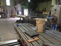
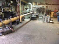
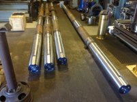
We are building two new Propellars Shafts for one of the big Bolivar Ferrys in Galveston. They are 39 ft long, 10inch in diameter.

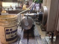
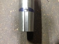
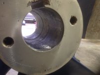
Here is how we cut the keyseats in the coupling end, and the Prop end. Both keyseats are in a taper at 1 inch in 12 inches.

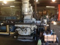
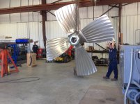
As you can see, the overhead crane takes all of the weight, the Mill pulls it along as it cuts.

http://benchrest.com/attachment.php?attachmentid=18904&stc=1&d=1485616159

http://benchrest.com/attachment.php?attachmentid=18905&stc=1&d=1485616204

http://benchrest.com/attachment.php?attachmentid=18907&stc=1&d=1485616257
 

Attachments

  • IMG_1581.JPG
    IMG_1581.JPG
    1.4 MB · Views: 1,375
  • IMG_1582.JPG
    IMG_1582.JPG
    1.4 MB · Views: 1,238
  • IMG_1583.JPG
    IMG_1583.JPG
    1.5 MB · Views: 1,289
4 liddle pieces of 5/8 allthread holding that barrel block and the crane bearing 5 tons in a single sling....'at there's a free-running gantry! You sure you don't need to have a guy tapping that traveler along with a broom?
 
Jackie, are the cutters square, or do they have a radius? We had problems with square keyway slots . Seems they would shear quicker then a slightly rounded one had to check them every year with die check.!
 
I didn't see any climb milling but I have a couple of questions.

I don't see anything holding the v block and my first assumption was that was aligned before the shaft went in. On the other hand the spacing on the threaded bar stock doesn't appear to match the t slot's on the table.

Is the bucket on the table for surplus coolant until the pump is turned off?

My wife came into the den while I had your picture's on full screen and asked me what I was looking at. I told her it was machinery porn. I got one of those look's and she walked away.....she know's me very well.
 
Jerry, I don't think the setup is rigid enough for climb milling, would seem to be risky.
When are you coming to RB?
Charlie
 
That's a little bigger than the sheer pin in my 5hp Evinrude circa 1950.
I could have said my Caille outboard but no one would know what I'm talking about.

Eureka! I found information on my old Caille with the adjustable pitch prop. How about that?


http://caille.8m.com/model-109/model-109-index.html


Sent from my iPad
Francis Becigneul

I did meet someone awhile back who I think would know about your motor. He had a dozen or so outboard motors mounted on stands in his shop. He also restored old motorcycles.
 
Climb milling?

.

The head is locked once depth of the key is determined. The table feeds the shaft into the cutter. The key is sized, after roughing it out within about 1/32 to the side, with the same cutter. The final width is 2 inches, the depth, 1 inch.

This is in truth a stout setup. The stagger tooth cutter keeps chatter and tool load down

We do Shafts that are less than 35 feet long in our #6 Kearney &Trecker Verticle Mill with regular end mill, supporting the shaft in the same manner.

http://benchrest.com/attachment.php?attachmentid=18916&stc=1&d=1485652668
 

Attachments

  • IMG_0616.JPG
    IMG_0616.JPG
    1.3 MB · Views: 628
Last edited:
Jackie, are the cutters square, or do they have a radius? We had problems with square keyway slots . Seems they would shear quicker then a slightly rounded one had to check them every year with die check.!

The keyseat in the shaft and the keyway in the Coupling have approx a 1/8 radius in the corner as required by The ABS.
 
I didn't see any climb milling but I have a couple of questions.

I don't see anything holding the v block and my first assumption was that was aligned before the shaft went in. On the other hand the spacing on the threaded bar stock doesn't appear to match the t slot's on the table.

Is the bucket on the table for surplus coolant until the pump is turned off?

My wife came into the den while I had your picture's on full screen and asked me what I was looking at. I told her it was machinery porn. I got one of those look's and she walked away.....she know's me very well.

The bottom of the V-Block has alignment dowels that fit the slots in the table. There are also four socket head cap screws aligned with a slot that attachs the V-Block to the table.

The bucket holds the water soluble coolant that feeds the mist cooler.
 
We do Shafts that are less than 35 feet long in our #6 Kearney &Trecker Verticle Mill with regular end mill, supporting the shaft in the same manner.

http://benchrest.com/attachment.php?attachmentid=18916&stc=1&d=1485652668


Foe the newbies to machining, cutting a keyway with an endmill doesn't result in the same force as climb milling with a circle cutter.

Love the K&T mills. In years past I spent some time with Theodore Trecker snow machine racing down by the Milwaukee airport. We had several of the big K&T horizontals including a 12' x 12' floor type mill. (124 yards of concrete just in its foundation). 85 HP, that sucker could take a 85 hp cut 12' above the table.


.
 
So does that get a gib head key?

No. The fit is on a one inch taper per foot, the Coupling, (and the propellar), are on corresponding tapers. The end of the shaft will have four 1 inch holes drilled and tapped in it which will secure a plate that tightens and securers the taper fit. Here are some 8 inch Shafts that have finished ends.

http://benchrest.com/attachment.php?attachmentid=18923&stc=1&d=1485752461

Here is the finish d keyseat in this shaft.

http://benchrest.com/attachment.php?attachmentid=18924&stc=1&d=1485752662
 

Attachments

  • IMG_0617.JPG
    IMG_0617.JPG
    1.4 MB · Views: 567
  • IMG_1584.JPG
    IMG_1584.JPG
    1.4 MB · Views: 491
Last edited:
Do you lap the prop. to fit the tapered shaft? We found that it helps to keep the prop tight when going from forward to reverse![/QUOTE

No, what we do is hand fit the Prop and The coupling tapers to the shaft. This is another specialty item we perform.

Many times, after they rework Props, the tapers can exhibit considerable warpage. They have to be hand ground back to fit. Here is a large prop we fitted to a 13 inch shaft we rebuilt.

http://benchrest.com/attachment.php?attachmentid=18925&stc=1&d=1485793139

You can see why "lapping", in the traditional sense, is not an option on pieces this large.

Here is a typical Prop bore that is just about ground in. Sometimes two men will take 2-3 days to get it right.that means you have to install the Prop, ( or Coupling), countless times to get an impression to where to grind.

http://benchrest.com/attachment.php?attachmentid=18926&stc=1&d=1485793559


Of course, we are set up to do all of this.
 

Attachments

  • IMG_1188.JPG
    IMG_1188.JPG
    1.5 MB · Views: 584
  • IMG_1572.JPG
    IMG_1572.JPG
    986.7 KB · Views: 532
Last edited:
I learned to hand scrape ways on machinery when I went through my apprenticeship and reworked a fair number of machines years ago. After seeing the picture of that prop, and its size, only one thought popped in my head. Screw that!
 
Last edited:
What are you using for grinding? Do you just reach in there with an air tool and kiss the high spots?
 
Last edited:
What are you using for grinding? Do you just reach in there with an air tool and kiss the high spots?

In simplistic terms, that is xactly what you do. We use large bullet wheel grinders and barrel sanders to remove the metal.

The trick is to be able to install and remove the propellor in order to get an accurate reading as to what is actually transfer of the Prussian Blue as opposed to "false readings".

This is very labor intensive. As you can see, we have the proper tools and set- up to do this, as well as the trained men. We can install and remove a Prop in a matter of minutes in order to get a reading.

We get propellers and Shafts in from other shops or shipyards that we are doing nothing else with solely for the purpose of fitting the Prop to the Shaft. It's another one of those specialty things we do that nobody else seems to want to do.
 
Back
Top