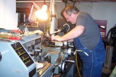
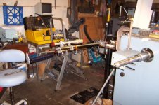
Chambering through a long headstock the Shelly Davidson way.

H

huntinco

Guest
Ok, because I never met him in person or anyone that was there to actually watch his chambering method, this is how I’m guessing he did it. As you can see, his Victor lathe, that I now own, is long through the headstock, but has a large enough ID to accommodate any bore.
LONG-HEADSTOCK-VICTOR-LATHE.JPG

So here is what I gather in a nut shell.
ALL-THREE-PARTS.JPG

First, he machined a bushing that fits snug inside the headstock spindle bore. Then one end of the bushing is machined a little undersized to allow for adjustment/ movement inside the spindle bore
SPINDLE-ID-BUSHING.JPG

He then machined a long tube that also fits snug inside the ID of the bushing and long enough to fit through the spindle.
HOLLOW-ADJUSTMENT-TUBE.JPG

This tube also has a hollow center on the pointed end that fits into the crown end of the barrel. On that back end of this tube there is a fitting to accommodate air or coolant into the barrel to clean out the chamber while it is being reamed.
HOLOW-TUBE-CROWN-END.JPG


TUBE-FITTING-FOR-BACK-END.JPG

At the back end of the spindle bore he machined a long spider for the tube to fit in that would allow for adjustment, by applying torque to this end it was transferred along the tube that was centered in the spindle bore by the bushing, where the pointed end would fit snug into the barrel and make it possible to adjust the crown end while it was inside the spindle bore.

I’m also assuming the reason for this set up was to align the chamber end to be reamed using the Gordy method and still be able to indicate the crown end while it is inside a spindle.
SPINDLE-SPIDER.JPG

SPINDLE-BORE-BACK-END.JPG

SPINDLE-BACK-END-WITH-SPIDER.JPG

As far as the spider that he made attached to a bearing I have no idea what he used this for.
SPIDER-BERING.JPG

I have yet to chamber a barrel with this lathe because I want everything just right. So far I built a 60X100 shop around the lathe, made a few bushings for the tractor, and accurized 2 actions. What a waste!!! Its time to make a rifle or two,

Feedback please!!!!!

Maybe Butch can help us out on this one.
 
Last edited by a moderator:
First question, how did that lathe get all the way to Utah? Just curious.

Ok, you seem to have most of it figured out, at least the part about doing the tenon and chamber end.

This type lathe setup generally has something like the following steps.

1-Slip a bushing on the chamber end to align it in the spindle bore while you chuck the muzzle end, indicate the muzzle end, cut off any excess (leave about 1" or so to cut off later).
(For example, of you are using a Kreiger/Bruno medium which comes about 29" long, you will generally cut off 6" or so from the muzzle end for a barrel that is to finish 22".)

2-Turn the barrel around, slip a bushing on the muzzle end and chuck and align the chamber end. The tenon end should extend from the chuck jaws by an amount that is the total of the tenon length + the amount you want to cut off where the lap started + about 3/4" for clearance to be able to work up to the tenon shoulder without crashing (about 1/2"-3/4"). Indicate the bore carefully and turn and thread the tenon, cut the chamber, and machine the cone. (Not necessarily in that order.)

3-Turn the barrel back around and slip or thread a bushing on the finished tenon while you finish the muzzle end. At this step, cut off the remainder of the excess, reindicate the muzzle bore and machine the crown.

You are not going to be able to use the GG method if the barrel is shorter than the spindle shaft and chuck, at least not as I'm seeing it so far. Most bushing/chuck setups use a bushing that fits on a straight turned part of the muzzle while doing the chamber end.

Have I missed anything? I'm typing and loading the camper at the same time!!
 
Last edited:
I drove to Texas built a skid frame on site and winched it into my trailer! Man trying to drag a big lathe up on a trailer took a lot of force 17,000lbs of pull.. Then I built a crate around it and brought it home.. In this set up the pointed end of the tube rides in the center of barrel on the crown end... In short it works the same as the Gordy way right? Adjusting the spyder end transfers movement along the tube into the center of the crown, then that center plus the chamber end of the barrel will also slightly adjust. right? I read the other long head stock posts but this set up in my mind works diffrent
 
Last edited by a moderator:
I have added a few more pictures that might help
#1 Removable bushing with a that fits snug inside the spindle bore ID and the OD of #3.
#2 Spider that rides on the back end of the lathe and adjusts #3 changing the alignment of # 4
# 3 Alignment tube with a drilled out center for coolant into the bore and a tapered end that rides into the bore center for adjustable alignment coming from the spider end
# 4 Barrel crown of a bore.


LATHE2.JPG

LATHE-3.JPG
 
Last edited by a moderator:
Hunt, thank you for posting this, a picture is worth a thousand words.
 
Could that spider on the bearing been used in the steadyrest? Is that it in the first picture?...If so it looks like the steadyrest(maybe without the rollers) could be tightened around the brass looking bushing and then the work held with the spider screws.
 
Last edited:
I've got one of those Victor lathes at work.........I was talking to the machinery dealer that sold it new and he said the gears in the early production of that lathe were made and ground in Japan, until the Taiwanese manufacturer learnt how to make gears.
I really like my Victor.............Ian
 
I chambered my first barrel on that lathe a few years ago. The end of the lathe held a tapered pilot that fit into the muzzle, then he pushed the barrel back until he had about two inches of the chamber end sticking out then tighted it down then he indicated the chamber an went from there. Shelley didn't like the flush system because he said he'd get covered in oil along with his shop.

Jeff Aberegg
 
Thanks Jeff. So I'm assuming if he did not want coolant every where he used some sort of fitting to provide continued air pressure. What about this spider Bering? I also think It was use I'n the steady rest. Again thanks for the info.
 
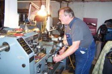
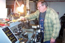
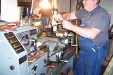
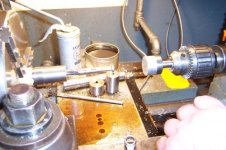
Here are a couple of photo's of Shelley chambering a barrel. Nothing special but, hopefully you can get an idea.
 

Attachments

  • 100_1283.jpg
    100_1283.jpg
    32.9 KB · Views: 1,022
  • 100_1272.jpg
    100_1272.jpg
    33.6 KB · Views: 941
  • 100_1281.jpg
    100_1281.jpg
    33.9 KB · Views: 908
  • 100_1275.jpg
    100_1275.jpg
    33.1 KB · Views: 978
  • 100_1280.jpg
    100_1280.jpg
    31.1 KB · Views: 884
  • 100_1282.jpg
    100_1282.jpg
    34.5 KB · Views: 957
Thanks Jeff......very enlightening.

Looking at the last photo it looks like adapter #2, as pictured in the previous photos, is used to dial in the tube, #3 in the previous photos, since I can't see inside the spindle it would be my guess that the bushing #1 is inside the spindle and the tube #3 is pivoting on this point and when the end of the tube outside the spider is adjust true the pointed end of the tube would also be running true or very near too it. Depending how far in the headstock bushing #1 goes and how long the tube #3 is you could probably do some pretty short barrels.
I see he is also using a 4 jaw chuck with no top jaws on it..........This is all just a guess and I may be totally wrong....................Ian
 
Back
Top